VS1005g Datasheet
10 VS1005 PERIPHERALS AND REGISTERS
DEC6_LEFT, DEC6_LEFT_LSB, DEC6_RIGHT and DEC6_RIGHT_LSB are the FM demodu-
lator output data registers. Sample rate @12.288 MHz is 32 kHz (xtal / 384).
10.17.3 Radio Data System (RDS)
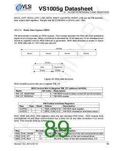
FM demodulator includes an RDS module. This module decodes the RDS bits from baseband
signal to form bit groups. When a full block is decoded the 16-bit data and 10-bit checkword are
stored to registers and an RDS-interrupt is generated. RDS data structure is shown in figure
19. RDS data rate is 1187.5 bits per second.
Figure 19: RDS data structure
RDS module’s control bits are in register FM_CF.
RDS Control Bits in Register FM_CF (address 0xFE40)
Name
Bit Index Description
FM_CF_RDSSYNC
FM_CF_RDSENA
5
2
FM RDS forced to keep current bit synchronization
FM RDS enable
FM Control and Data Registers
Type Reset Abbrev Description
Reg
0xFE52
0xFE53
r
r
0
0
RDS_DATA[15:0] FM RDS data register
RDS_CHK[12:0] FM RDS checkwork and block status
RDS_DATA and RDS_CHK registers store the last decoded RDS block. RDS module finds
automatically bit and block synhronization but it does not do any data correction if crc errors
exist. This must be done by software.
RDS_CHK Register Bits
Reg
Bit index
Name Description
RDS_CHK_CHKW
RDS_CHK_ST
12:3
2
CHECKWORD Checkword of the last received block data
STATUS Validity of the last received block
RDS_CHK_BLK
1:0
BLOCK Index of the last received block, 0-3
Version: 0.2, 2012-03-16
89

 ETC [ ETC ]