Freescale Semiconductor, Inc.
Software Design
Algorithm of Dead Time Distortion Correction
DC-Bus Over-voltage: In case of DC-Bus over-voltage, the external
hardware provides a rising edge on the DC-Bus over-voltage fault input
of the microcontroller. This signal disables all motor montrol PWM
outputs (PWM1 - PWM6) and sets the application fault status.
DC-Bus Under-voltage: The sensed DC-Bus voltage is compared with
the limit within the software. In case of DC-Bus under-voltage, all motor
control PWM outputs (PWM1 - PWM6) are disabled and the application
fault status is set.
If any of the faults occurs, the application status is changed into the Fault
Status.
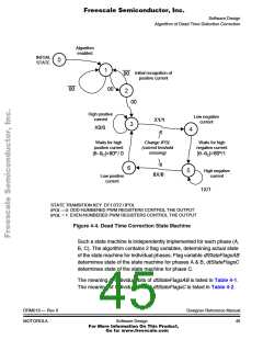
4.3.7 Dead Time Distortion Correction
The process defines the value registers to be used for PWM generation
according to the type of dead time distortion correction and the state of
the immediate phase current polarity.
• If no dead time correction is required, the PVAL1,3,5 are used, the
complementary PVAL values are calculated by on-chip PWM
peripheral automatically.
• If partial dead time correction is required, the PVAL value is
selected by on-chip PWM peripheral automatically according to
the phase current polarity sensing
• If full dead time correction is required, the process selects the
desired PVAL registers according to the dead time distortion
correction state machine.
In the following section the dead time distortion correction algorithm is
described in detail.
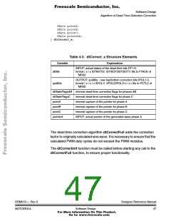
4.4 Algorithm of Dead Time Distortion Correction
The algorithm dtCorrectFull calculates the IPOL bits defining the PVAL
registers to be used for MC68HC908MR32 PWM generation for full dead
time correction. The IPOL bits are determined according to the phase
DRM019 — Rev 0
MOTOROLA
Designer Reference Manual
Software Design
43
For More Information On This Product,
Go to: www.freescale.com

 ETC [ ETC ]