Freescale Semiconductor, Inc.
Software Design
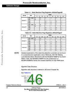
Table 4-1. State Machine Flag Registers dtStateFlagsAB
State
phase
bits
1
2
3
4
5
6
bit0 - lock
bit1
0
0
0
1
1
1
1
1
phase A
bit2
bit3
bit4 - lock
bit5
bit6
0
0
1
1
0
1
0
1
1
1
1
1
0
0
0
1
phase B
0
0
1
0
0
1
1
1
bit7
Table 4-2. State Machine Flag Registers dtStateFlagsC
State
phase
bits
1
2
3
4
5
6
bit0 - lock
bit1
0
0
0
1
1
1
1
1
phase C
reserved
bit2
bit3
bit4
0
0
x
x
x
x
1
0
x
x
x
x
0
1
x
x
x
x
1
1
x
x
x
x
x
x
x
x
x
x
x
x
bit5
bit6
bit7
NOTE: Detailed explanation of the dead time distortion correction can be found
in a comprehensive application note of Motorola, AN1728 “Making
Low-Distortion Motor Waveforms with the MC68HC708MP16“ by David
Wilson. Note, that MC68HC708MP16 is the predecessor of
MC68HC908MRxx family and contains identical on-chip PWM block.
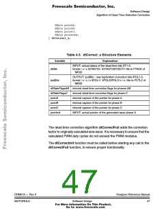
Algorithm Data Structure:
Algorithm data structure is defined in dtCorrect.h header file.
See Table 4-3.
typedef struct {
UByte dtBits;
UByte ipolBits;
type_uBits dtStateFlagsAB;
type_uBits dtStateFlagsC;
Designer Reference Manual
46
DRM019 — Rev 0
MOTOROLA
Software Design
For More Information On This Product,
Go to: www.freescale.com

 ETC [ ETC ]