Freescale Semiconductor, Inc.
Software Design
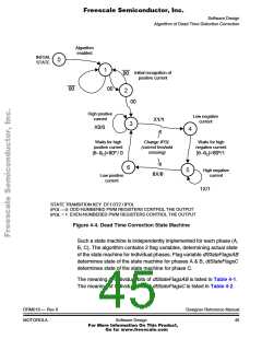
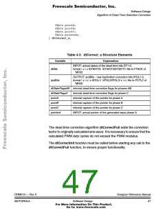
current polarity detection bits DT1-6, actual sine wave pointer, and the
actual state of the algorithm state machine.
The algorithm state machine samples the actual state of the phase
current, and selects appropriate PVAL registers to be used for PWM
generation. The state machine, implemented in the dtCorrectFull
algorithm, is illustrated in Figure 4-4.
When the algorithm is enabled, the state machine is entered from initial
state 0. It is waiting till the high magnitude of positive current is detected
(State 1, confirmed by State 2), then the algorithm enters the state
machine (State 3). The state machine is performed in circle 3-4-5-6-3.
As soon as the low magnitude of negative current is detected, the IPOL
is changed to 1, requesting the even-numbered PWM registers to be
used for PWM generation, the actual value of the wave pointer is
recorded (θ ), and State 4 is entered. State 4 is preserved for 80
C
electrical degrees, until a high negative current can be expected. Then
State 5 is entered. As soon as the low magnitude of positive current is
detected, the IPOL is changed to 0, requesting the odd-numbered PWM
registers to be used for PWM generation, the actual value of the wave
pointer is recorded (θ ), and State 6 is entered. State 6 is preserved for
C
80 electrical degrees, until a high positive current can be expected. Then
State 3 is entered and the state machine loop is repeated. In this way, it
is ensured that the required IPOL changes when a small amplitude of
respective current is detected by the hardware. Please note, that the
wave pointer is recorded into the algorithm variable PointA, PointB, or
PointC, in the moment when the respective phase current crosses the
low current threshold.
Designer Reference Manual
44
DRM019 — Rev 0
Software Design
MOTOROLA
For More Information On This Product,
Go to: www.freescale.com

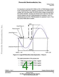
 ETC [ ETC ]