Freescale Semiconductor, Inc.
Software Design
Algorithm of Dead Time Distortion Correction
SByte pointA;
SByte pointB;
SByte pointC;
SByte pointerA;
} dtCorrect_s;
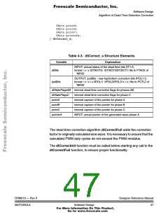
Table 4-3. dtCorrect_s Structure Elements
Variable
dtBits
Explanation
INPUT: actual status of the dead time bits DT1-6,
format | x | x |DT6|DT5| |DT4|DT3|DT2|DT1| fits to FTACK of
‘MR32
OUTPUT: ipolBits - new top/bottom correction bits IPOL1-3,
format | x | x | x |IPOL1| |IPOL2|IPOL3| x | x | fits to PCTL2 of
‘MR32
ipolBits
dtStateFlagsAB internal dead-time correction flags for phases AB
dtStateFlagsC
pointA
internal dead-time correction flags for phase C
internal capture of the pointer for phase A
internal capture of the pointer for phase B
internal capture of the pointer for phase C
INPUT: actual pointer of the generated wave phase A
pointB
pointC
pointerA
The dead time correction algorithm dtCorrectFull adds the correction
factor to originally calculated sine wave. It is necessary to ensure that the
calculated PWM duty cycles do not exceed the PWM modulus.
The dtCorrectInit function must be called before starting any call to the
dtCorrectFull function, to ensure proper functionality.
DRM019 — Rev 0
MOTOROLA
Designer Reference Manual
Software Design
47
For More Information On This Product,
Go to: www.freescale.com

 ETC [ ETC ]