Freescale Semiconductor, Inc.
Software Design
• Phase B — sPhaseVoltage.PhaseB
• Phase C — sPhaseVoltage.PhaseC
°
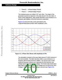
The individual waves are shifted 120 each other. The shape of the
generated waveforms depends on the data stored in the sine table. In
motor control applications, data usually describes a pure sinewave or a
sinewave with addition of the third harmonic component.
Figure 4-2 shows the duty cycles generated by the
mcgen3PhWaveSine function when amplitude is 50%.
1.0
0.9
0.8
0.7
0.6
0.5
0.4
0.3
0.2
0.1
0.0
DutyCycle.PhaseA
DutyCycle.PhaseB
DutyCycle.PhaseC
Figure 4-2. 3-Phase Sine Waves with Amplitude of 50%
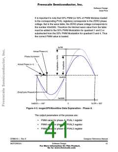
The calculation is based on the wave table stored in FLASH memory of
the microcontroller. The table describes either a pure sinewave or a
sinewave with the third harmonic addition. The second case is often
preferred because it allows one to generate the first harmonic sine
voltage equal to the input AC line voltage. The format of the stored wave
table data is from #0x0000 (for ZERO Voltage) up to 0x7fff (for the 100%
Voltage). Thus the proper data scaling is secured (see Figure 4-3).
Designer Reference Manual
40
DRM019 — Rev 0
MOTOROLA
Software Design
For More Information On This Product,
Go to: www.freescale.com

 ETC [ ETC ]