Freescale Semiconductor, Inc.
Software Design
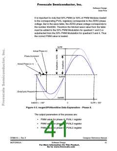
In case of dead time distortion correction, the corrected PVAL values
PVAL1-6 are calculated and used for the PWM generation according to
the detected phase current polarity.
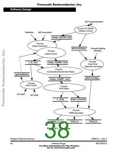
The process can be described by following points:
• Wave pointer for phase A is updated by the table increment.
• Based on the wave pointer, the PWM values for all three phases
are calculated.
• PWM values are rescaled according to the PWM modulo (PWM
frequency) and loaded into PVAL1, 3, 5 registers. Registers
PVAL2, 4, 6 are loaded automatically because of complementary
PWM mode selected during the PWM module initialisation.
• In case of dead time distortion correction, the corrected values
PVAL1-6 are calculated and used for PWM generation according
to the detected phase current polarity.
The process is accessed regularly in the rate given by the set PWM
frequency and the selected PWM interrupt prescaler.
4.3.5 PC Master Software Control
The process provides SCI communication with PC using PC master
software service routines. These routines are fully independent on the
motor control tasks. They enable for example to set the desired speed,
the PWM frequency and the type of dead time distortion correction.
4.3.6 Fault Control
This process is responsible for fault handling. The software
accommodates three fault events: DC-Bus over-current, DC-Bus
over-voltage and DC-Bus under-voltage.
DC-Bus Over-current: In case of DC-Bus over-current, the external
hardware provides a rising edge on the DC-Bus over-current fault input
of the microcontroller. This signal disables all motor control PWM
outputs (PWM1 - PWM6) and sets the application fault status.
Designer Reference Manual
42
DRM019 — Rev 0
Software Design
MOTOROLA
For More Information On This Product,
Go to: www.freescale.com

 ETC [ ETC ]