Freescale Semiconductor, Inc.
Software Design
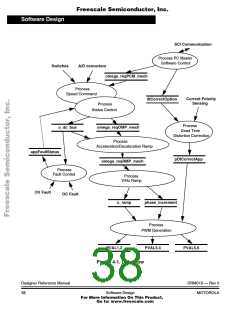
Data Flow
4.3.1 Speed Command & Status Control
In the Manual Operating Mode, the required speed is set by speed
potentiometer and switches (start/stop, forward/reverse). In the PC
Master Software (Remote) Operating Mode, the required speed is set by
PC. In the process, the input parameters are evaluated and the speed
command is calculated accordingly. Also the DC-Bus voltage is
measured. The application fault status is analyzed and the state of the
drive is set. The status LED’s are controlled according to the system
state.
4.3.2 Acceleration/Deceleration Ramp
The process calculates the new speed command based on the required
speed according to the acceleration / deceleration ramp.
4.3.3 V/Hz Ramp
This process provides voltage calculation according to V/Hz ramp. The
input of this process is the generated inverter frequency
omega_req_RMP_mech. The outputs of this process are the output sine
wave parameters required by PWM generation process: the table
increment phase_increment that corresponds to the frequency
omega_req_RMP_mech and is used to roll through the wave table in
order to generate the output inverter frequency, and the corresponding
amplitude of the generated inverter voltage u_ramp.
4.3.4 Process PWM Generation
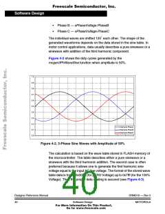
This process generates a system of three phase sinewaves shifted 120
o
each other. The function mcgen3PhWaveSine is used for the sine wave
calculation.
The mcgen3PhWaveSine function calculates an immediate value of the
three-phase sinusoidal system from given amplitude and actual phase
pointer:
• Phase A — sPhaseVoltage.PhaseA
DRM019 — Rev 0
MOTOROLA
Designer Reference Manual
Software Design
39
For More Information On This Product,
Go to: www.freescale.com

 ETC [ ETC ]