Freescale Semiconductor, Inc.
System Description
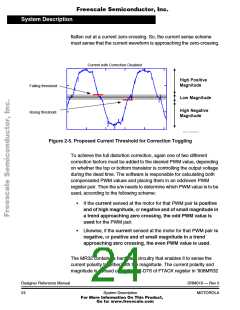
To achieve distortion correction, one of two different correction factors
must be added to the desired PWM value, depending on whether the top
or bottom transistor is controlling the output voltage during the dead
time.
When the voltage pulse is shortened due to dead time, the control PWM
signal is extended by dead time, so the actual voltage pulse matches the
desired voltage. Vice versa, when the voltage pulse is lenghtened due to
dead time, the control PWM signal is shortened by dead time, so again
the actual voltage pulse matches the desired voltage. Therefore the
actual signal equals the desired one, and the generated phase current
is sinusoidal.
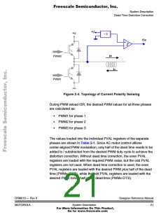
The dead time distortion correction utilizes phase current sensing. The
on-chip PWM module of MC68HC908MRxx microcontrollers contains
the block that enables them to evaluate the polarity and the size of the
phase current without the need of an expensive current sensor. It is
based on the sampling and evaluation of the phase voltage level during
the dead time. The zero voltage during dead time reflects a positive
phase current, the full DC-Bus voltage during dead time reflects a
negative phase current. So comparing the phase voltage with the half
DC-Bus voltage enables an evaluation of the current polarity. The
topology is illustrated in Figure 2-4. The output of the comparator is
connected to the current polarity sensing input of the MC68HC908MR32
microcontroller. The microcontroller contains the hardware that samples
the current sensing inputs during dead time. It enables evaluation of the
current polarity and also the region of low currents.
Designer Reference Manual
20
DRM019 — Rev 0
System Description
MOTOROLA
For More Information On This Product,
Go to: www.freescale.com

 ETC [ ETC ]