Freescale Semiconductor, Inc.
System Description
The PWM frequency can be changed at any time during the motor
operation to one of the following values:
– 4kHz
– 8kHz
– 16kHz
– 32kHz
The drive incorporates fault protection, so in the case of DC-Bus
over-current, DC-Bus over-voltage, or DC-Bus under-voltage faults,
internal fault logic is asserted and the application enters a fault state.
This state can be exited only if the fault disappears and it is
acknowledged, by toggling the START/STOP switch through the STOP
state. The application states are displayed by green LED on 908MR32
control board.
The application can operate in two modes:
1. Manual Operating Mode
The drive is controlled by the START/STOP switch. The direction
of the motor rotation is set by the FWD/REV switch. The motor
speed is set by the SPEED potentiometer.
2. PC Master Software (Remote) Operating Mode
The drive is controlled remotely from a PC through the serial
communications interface (SCI) communication channel of the
MCU device via an RS-232 physical interface. The drive is
enabled by the START/STOP switch, which can be used to safely
stop the application at any time.
2.3 Dead Time Distortion Correction
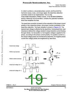
Six-transistor inverter is the most used topology for AC motor drives. The
dead time must be inserted between the turning off of one transistor in
the inverter half bridge and turning on of the complementary transistor.
The dead time causes distortion to the generated voltage, and thus a
non-sinusoidal phase current.
Designer Reference Manual
18
DRM019 — Rev 0
System Description
MOTOROLA
For More Information On This Product,
Go to: www.freescale.com

 ETC [ ETC ]