Freescale Semiconductor, Inc.
System Description
Dead Time Distortion Correction
The on-chip PWM module of MC68HC908MRxx microcontrollers
enables them to perform two types of dead time distortion correction:
• Partial correction
• Full correction
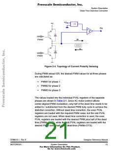
Partial dead time distortion correction is based only on polarity
detection of phase current. The hardware, sensing the current polarity
according to Figure 2-4, needs to be implemented. The software is
responsible for calculating both compensated PWM values and placing
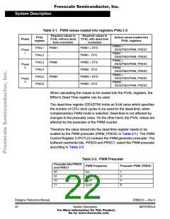
them in an odd/even PWM register pair according to Table 2-1. The
distortion correction is fully implemented by the on-chip PWM module
according to the following scheme:
• If the current sensed at the motor for that PWM pair is positive
(voltage on current pin ISx is low), the odd PWM value is used
for the PWM pair.
• Likewise, if the current sensed at the motor for that PWM pair is
negative (voltage on current pin ISx is high), the even PWM
value is used.
For partial correction, the on-chip dead time correction block is set in the
automated mode - current sense correction bits ISENS1:ISENS0 of
PWM Control Register 0 (PCTL1) are set to 10).
The disadvantage of the partial correction is that some dead time
distortion still exist - the current is flattened out at the zero crossings.
Full dead time distortion correction (implemented in dtCorrectFull
algorithm) improves the partial dead time correction by sensing not only
the polarity, but also the magnitude of the actual phase current.
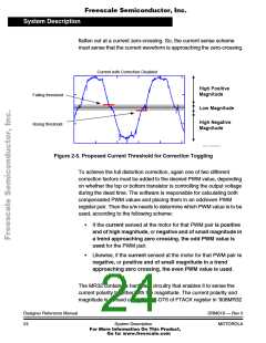
In the full dead time correction method, the threshold, where the
correction values should be toggled is not in the zero level, but slightly
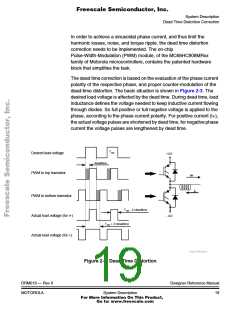
advanced. The threshold is illustrated in Figure 2-5. Toggling of the
correction offset needs to occur before the current has a chance to
DRM019 — Rev 0
MOTOROLA
Designer Reference Manual
System Description
23
For More Information On This Product,
Go to: www.freescale.com

 ETC [ ETC ]