Freescale Semiconductor, Inc.
System Description
Dead Time Distortion Correction
In order to achieve a sinusoidal phase current, and thus limit the
harmonic losses, noise, and torque ripple, the dead time distortion
correction needs to be implemented. The on-chip
Pulse-Width-Modulation (PWM) module, of the MC68HC908MRxx
family of Motorola microcontrollers, contains the patented hardware
block that simplifies the task.
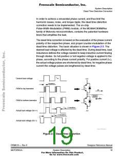
The dead time correction is based on the evaluation of the phase current
polarity of the respective phase, and proper counter-modulation of the
dead-time distortion. The basic situation is shown in Figure 2-3. The
desired load voltage is affected by the dead time. During dead time, load
inductance defines the voltage needed to keep inductive current flowing
through diodes. So full positive or full negative voltage is applied to the
phase, according to the phase current polarity. For positive current (i+),
the actual voltage pulses are shortened by dead time, for negative phase
current the voltage pulses are lengthened by dead time.
TON
Desired load voltage
PWM to top transistor
+U/2
deadtime
i+
i-
PWM to bottom transistor
Actual load voltage (for i+)
Actual load voltage (for i-)
TON - 2×deadtime
- U/2
TON + 2×deadtime
Dave Wilson
Figure 2-3. Dead Time Distortion
DRM019 — Rev 0
MOTOROLA
Designer Reference Manual
System Description
19
For More Information On This Product,
Go to: www.freescale.com

 ETC [ ETC ]