Freescale Semiconductor, Inc.
System Description
System Concept
Phase
Voltage
Base
Point
100%
Boost
Voltage
Boost
Frequency
Base
Frequency
Frequency (rpm)
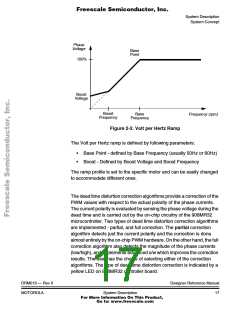
Figure 2-2. Volt per Hertz Ramp
The Volt per Hertz ramp is defined by following parameters:
• Base Point - defined by Base Frequency (usually 50Hz or 60Hz)
• Boost - Defined by Boost Voltage and Boost Frequency
The ramp profile is set to the specific motor and can be easily changed
to accommodate different ones.
The dead time distortion correction algorithms provide a correction of the
PWM values with respect to the actual polarity of the phase currents.
The current polarity is evaluated by sensing the phase voltage during the
dead time and is carried out by the on-chip circuitry of the 908MR32
microcontroller. Two types of dead time distortion correction algorithms
are implemented - partial, and full correction. The partial correction
algorithm detects just the current polarity and the correction is done
almost entirely by the on-chip PWM hardware. On the other hand, the full
correction algorithm also detects the magnitude of the phase currents
(low/high), and implements advanced s/w which improves the correction
results. The user has the choice of selecting either of the correction
algorithms. The type of dead time distortion correction is indicated by a
yellow LED on 908MR32 controller board.
DRM019 — Rev 0
MOTOROLA
Designer Reference Manual
System Description
17
For More Information On This Product,
Go to: www.freescale.com

 ETC [ ETC ]