Freescale Semiconductor, Inc.
System Description
3-phase AC Power Stage
AC
ACM
DC
DC Bus Voltage
Polarity of
LOAD
DC Bus Current
Phase
PWM’s
Temperature
Currents
MC68HC908MR32
I sense
Fault Protection
Desired Sine
Dead Time
Correction
- Disabled
- Partial
Frequency
V/Hz
Dead
Time
Ramp
START
Sine PWM
Generation
STOP
Req.
Desired
Speed
Correction
State
Speed
Speed
Ramp
Machine
- Full
DOWN
Desired Sine
Amplitude
Desired
Correction
of PWM’s
UP
PC Control
SCI
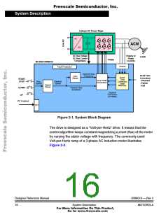
Figure 2-1. System Block Diagram
The drive is designed as a “Volt-per-Hertz“ drive. It means that the
control algorithm keeps constant magnetizing current (flux) of the motor
by varying the stator voltage with frequency. The commonly used
Volt-per-Hertz ramp of a 3-phase AC induction motor illustrates
Figure 2-2.
Designer Reference Manual
16
DRM019 — Rev 0
System Description
MOTOROLA
For More Information On This Product,
Go to: www.freescale.com

 ETC [ ETC ]