Freescale Semiconductor, Inc.
Designer Reference Manual — 3-ph. ACIM Drive with DTC
Section 2. System Description
2.1 Contents
2.2
2.3
System Concept . . . . . . . . . . . . . . . . . . . . . . . . . . . . . . . . . . . .15
Dead Time Distortion Correction . . . . . . . . . . . . . . . . . . . . . . .18
2.2 System Concept
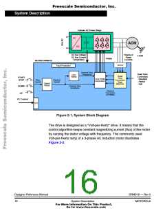
The application is designed to drive a 3-phase AC motor in an open
speed loop mode with dead time distortion correction (see Figure 2-1).
The desired speed is set-up in the user interface. The desired frequency
and amplitude of the motor voltage sine wave is calculated according to
the desired speed using Volt-per-Hertz table. The sine wave generator
generates the PWM values for all three phases of the AC bridge inverter
according to the selected type of dead time distortion correction
algorithm.
The system incorporates the following hardware blocks:
• power supply rectifier,
• three-phase inverter including optoisolation,
• feedback sensors: DC-Bus voltage, DC-Bus current, temperature,
polarity of phase currents,
• microcontroller MC68HC908MR32.
DRM019 — Rev 0
MOTOROLA
Designer Reference Manual
System Description
15
For More Information On This Product,
Go to: www.freescale.com

 ETC [ ETC ]