Proprietary TranSwitch Corporation Information for use Solely by its Customers
L3M
TXC-03452B
DATA SHEET
Address
Bit
Symbol
Description
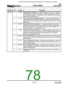
B6 & B7
7
L3ERR
Analyzer Error Indication: A 1 indicates that the 215-1 or 223-1 analyzer
has detected an error when enabled. A 1 written to ENANA (bit 3, location
C6) enables the analyzer. This indication will be disabled during operation
when control bit ENANA is a 0.
6
5
4
LOVFL
RFRST
TFRST
Leak FIFO Overflow/Underflow Alarm: A 1 indicates that the leak FIFO
has underflowed or overflowed. When this occurs, the FIFO will automati-
cally reset to a preset position and the FIFOERR output (lead 11 or F3) will
pulse high.
Receive FIFO Reset Indication: A 1 indicates that either of the receive
FIFOs has been reset. This may occur because of a FIFO overflow/under-
flow alarm, or when the receive section has been reset by writing a 1 to
control bit RXRST, or upon hardware reset.
Transmit FIFO Reset Indication: A 1 indicates that the transmit FIFO has
been reset. This may occur because of a FIFO overflow/underflow alarm, or
when the transmit section has been reset by writing a 1 to control bit
TXRST, or upon hardware reset.
3
2
1
0
VCXOLOC Loss of VCXO Clock: A 1 indicates that the external VCXO clock has been
stuck high or low for 1000 ± 500 nanoseconds. Recovery occurs on the first
clock transition.
TPLOC
Loss of Transmit PLL Clock: A 1 indicates that the internal PLL clock has
been stuck high or low for 1000 ± 500 nanoseconds. Recovery occurs on
the first clock transition.
RPLOC Loss of Receive PLL Clock: A 1 indicates that the internal PLL clock has
been stuck high or low for 1000 ± 500 nanoseconds. Recovery occurs on
the first clock transition.
OOL
Analyzer Out of Lock: A 1 indicates that the analyzer, when enabled, is
out of lock.
TXC-03452B-MB
Ed. 6, April 2001
- 78 of 96 -

 ETC [ ETC ]