Proprietary TranSwitch Corporation Information for use Solely by its Customers
L3M
TXC-03452B
DATA SHEET
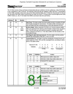
Address
Bit
Symbol
Description
Software Interrupt: A software interrupt indication occurs when one or
B4 & B5
7
SINT
(B4 only) more bit locations in the interrupt mask locations is set to 1, and the corre-
sponding latched alarm is active. The SINT state is exited when the latched
alarm causing the interrupt clears or its corresponding bit in the interrupt
mask is cleared.
6
FEBE9
FEBE Count of 9 Indication: An STS FEBE9 indication occurs when the
code 1001 (count of 9) in bits 1-4 in the received G1 byte is detected for five
consecutive frames. The alarm is terminated when any code other than the
1001 is detected in bits 1-4 for five consecutive frames.
5
4
NEW
New Alarm: An indication that a new J1 location, other than those resulting
from INC or DEC, has been detected.
TUG3NEW TUG-3 New Alarm: A TUG-3 new indication occurs when three consecu-
tive new pointers, or an NDF and a match of the SS bits and the pointer off-
set value is in range, has been detected.
3
ROVFL
Receive FIFO Overflow/Underflow: A 1 indicates an underflow or overflow
condition in the receive direction (SDH/SONET to line). When this happens,
the FIFO will automatically reset to a preset position and the FIFOERR out-
put (lead 11 or F3) will pulse high.
2
1
0
XSTAI
XISTAT
XPAIS
SDH/SONET Network Alarm Indication: A 1 indicates that the input on
the lead labeled STAI is high.
External STS-1 Alarm: A 1 indicates that the input on the lead labeled
ISTAT is a high. A 1 is equal to an external alarm condition (e.g., LOP).
External Path AIS: A 1 indicates that the input on the lead labeled PAIS is
a high. A 1 is equal to an external alarm condition (i.e., Path AIS).
TXC-03452B-MB
Ed. 6, April 2001
- 77 of 96 -

 ETC [ ETC ]