Proprietary TranSwitch Corporation Information for use Solely by its Customers
L3M
TXC-03452B
DATA SHEET
Address
Bit
Symbol
Description
B2 & B3
7
RDI
Receive RDI (Yellow) Alarm: When RDI5 is set to 0, a 1 in RDI indicates
that bit 5 in the G1 byte has been detected as a one for 10 consecutive
frames. When RDI5 is set to 0, RDI recovers to 0 when a 0 has been
detected for 10 consecutive frames. When RDI5 is a 1, detection and recov-
ery of RDI occurs after 5 consecutive events instead of 10.
6
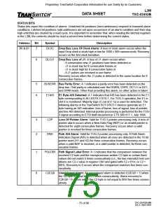
L3LOS
Mapper Transmit Loss Of Signal: For an E3 signal, a loss of signal alarm
occurs when the positive/negative rail is stuck low for 256 bit times. Recov-
ery occurs when there are at least 32 transitions (both positive and negative
rail) in a count of 256 clock cycles. For a DS3 signal, a loss of signal alarm
occurs when either the positive or negative rail is stuck low for 200 bit times.
Recovery occurs on the first transition (both positive and negative rail).
When the interface is configured for NRZ operation, an active high on the
TNEG will be an external loss of signal indication and will cause a L3LOS
indication.
5
4
3
L3LOC
TOVFL
L3AIS
Mapper Transmit Loss of Clock: A 1 indicates the incoming line clock
(TCLK) signal has been stuck high or low for 1000 ± 500 nanoseconds.
Recovery occurs on the first clock transition.
Transmit FIFO Overflow/Underflow: A 1 indicates that the transmit FIFO
has either underflowed or overflowed. When this happens, the FIFO auto-
matically resets to a preset position.
Mapper E3 Transmit AIS Detected: For an E3 signal, AIS is detected
when four or fewer zeros are detected in 1536 bits, twice in a row. Recovery
occurs when there are five or more zeros detected in 1536 bits two consec-
utive times.
2
1
RAMLOC Loss Of Microprocessor RAM Clock: A 1 indicates that the RAM clock
(RAMCI) has been stuck high or low for 1000 ± 500 nanoseconds. Recov-
ery occurs on the first clock transition.
ALOC
Add Bus Loss Of Clock: A loss of clock alarm occurs when the input add
clock (ACLK) is stuck high or low for 1000 ± 500 nanoseconds. Recovery
occurs on the first clock transition. When the add bus clock is an output, the
external byte clock (XCLKI) is monitored for loss of clock instead, and its
loss is reported by this alarm.
0
ALOJ1
Add Bus Loss of J1: A loss of J1 alarm occurs when:
- 8 consecutive new J1 positions have been detected or
- J1 is stuck low for 8 consecutive frames or
- J1 is stuck high for 8 consecutive bytes or
- 8 J1 pulses are received in one frame.
Recovery occurs when the J1 pulse is detected in the same location for 8
consecutive frames.
TXC-03452B-MB
Ed. 6, April 2001
- 76 of 96 -

 ETC [ ETC ]