Proprietary TranSwitch Corporation Information for use Solely by its Customers
L3M
TXC-03452B
DATA SHEET
STATUS BITS
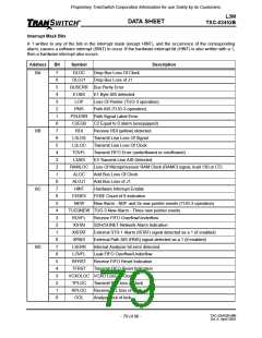
Status bits report the condition of alarms. Unlatched bit positions (even addresses) respond to transient alarm
conditions. Latched bit positions (odd addresses) are set upon occurrence of an alarm condition and then stay
high until they are cleared by a read cycle. It is important to remember that, when reading the latched registers
in the L3M, the contents should be read a second time before determining the current status.
Address
Bit
Symbol
Description
B0 & B1
7
DLOC
Drop Bus Loss Of Clock Alarm: A loss of clock alarm occurs when the
input Drop clock is stuck high or low for 1000 ± 500 nanoseconds. Recovery
occurs on the first clock transition.
6
DLOJ1
Drop Bus Loss of J1: A loss of J1 alarm occurs when:
- 8 consecutive new J1 positions have been detected or
- J1 is stuck low for 8 consecutive frames or
- J1 is stuck high for 8 consecutive bytes or
- 8 J1 pulses are received in one frame.
Recovery occurs when the J1 pulse is detected in the same location for 8
consecutive frames.
5
4
BUSERR Bus Parity Error: A 1 indicates a parity error has been detected on the
drop bus. Odd parity is calculated over the DDATA, DSPE, DC1J1 or DC1,
and DPAR leads. Other than providing this alarm, no other action is taken.
E1AIS
E1 Byte AIS Detected: A 1 indicates that AIS has been detected in the E1
byte corresponding to AU-3/STS-3 STS-1. For TUG-3 operation, the E1 in
slot 0 is monitored. Majority logic (5 out of 8 1s) is used for detection. The
following alarms in the TranSwitch SOT-3/SOT-1 devices generate an E1
byte having an AIS indication: loss of frame, loss of signal, loss of pointer,
and line AIS detected. Internal pointer processing is performed for the TUG-
3 signal according to ETSI draft document pr ETS 300 417-1, July 1994.
3
2
LOP
PAIS
Loss Of Pointer Alarm: Valid for TUG-3 pointer processing only. A loss of
pointer alarm occurs when a New Data Flag (NDF) or an invalid pointer is
detected for eight consecutive frames. Recovery occurs when a valid
pointer is received for three consecutive frames.
Path AIS Alarm: Valid for TUG-3 pointer processing only. A Path Alarm
Indication Signal (AIS) is detected when all ones are detected in the 16 bit
pointer word (H1 and H2) for three consecutive frames. Recovery occurs
when a valid NDF is received, or a valid pointer is detected, for three con-
secutive frames.
1
0
PSLERR Path Signal Label Error: A 1 indicates that the comparison between the
received C2 byte and the microprocessor-written C2 byte or certain fixed
values did not match 5 times consecutively (i.e., the two mismatch test con-
ditions are C2 ≠ value in register C8H and-gated with C2 ≠ 01H, or C2 =
00H). Recovery to 0 occurs when the comparison matches five times con-
secutively.
C2EQ0
Unequipped Alarm: An unequipped alarm is detected (C2EQ0 = 1) when
the C2 byte is equal to 00H 5 times consecutively. Alarm recovery to
C2EQ0 = 0 occurs when the C2 byte is not equal to 00H five times consec-
utively.
TXC-03452B-MB
Ed. 6, April 2001
- 75 of 96 -

 ETC [ ETC ]