Proprietary TranSwitch Corporation Information for use Solely by its Customers
L3M
TXC-03452B
DATA SHEET
Address
Bit
Symbol
Description
C5
(cont.)
1
WGDEC
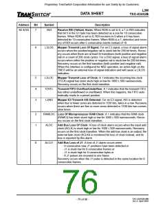
Test Equipment BPV Selection: A 1 enables the decoder to detect cod-
ing violations as found in ‘Type 1’ test equipment. A 0 enables the decoder
to detect coding violations as found in ‘Type 0’ test equipment. The follow-
ing tables summarize the two decoding procedures of coding violations:
BPV For B3ZS
BPV
"Type 1”
“Type 0”
Equipment
Equipment
++ or --
000 (preceding bit(s) changed)
11
011 or 0001
1101
0BV or 000V
BB0V after odd
B00V after even
0000
1000
1000
1001
BPV For HDB3
BPV
"Type 1”
“Type 0”
Equipment
Equipment
++ or --
0000 (preceding bit(s) changed)
11
011 or 00001
11001
0BV or 0000V
BB00V after odd
B000V after even
00000
10000
10000
10001
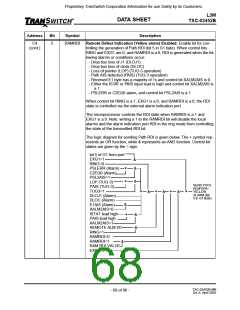
0
PSL2AIS Path Signal Label Error Enable AIS: A 1 enables the L3M device to send
DS3 or E3 AIS automatically towards the receive line, and path RDI
(FERF) when a PSLERR or C2EQ0 alarm occurs. (See RAMRDI and
RAISEN for diagrams.)
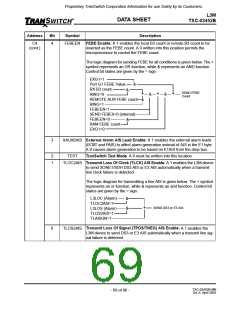
C6
7
6
FASTPTR Fast Pointer Enabled: A 1 allows the L3M device to track pointer move-
ments every frame instead of every other frame for TUG-3 operation.
TOHOUT Transport Overhead Bytes Out: A 1 enables the L3M device to generate
the A1, A2, C1, and the H1, H2 bytes, in the external timing mode (STS-1
mode) only. The H1 and H2 bytes are transmitted with a fixed pointer value
of 6000H.
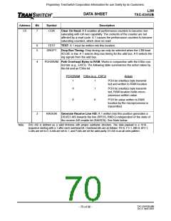
5
4
H4CTR
H4 Counter Enable: Normally set to 0. A 1 enables the H4 byte to be
transmitted with a count generated by an internal 8-bit frame counter.
223-1 Test Pattern Enable: A 0 selects the test pattern generators’ and
analyzer’s pattern to be 215-1. A 1 selects the pattern generators’ and ana-
lyzer’s pattern to be 223-1.
PAT23
3
2
ENANA
TXANA
Enable Analyzer: A 1 enables the 215-1or 223-1 analyzer. PRBS errors
are counted in a 16-bit counter in locations AEH and AFH.
Transmit Analyzer Enable: A 1 enables the analyzer to sample the trans-
mit NRZ line (DS3/E3) signal after the Decoder. A 0 causes the analyzer to
sample the receive NRZ line data prior to the coder function. A 1 must be
written into ENANA for this bit to function (see Figure 34).
1
0
TPRBS
RPRBS
Transmit Test Pattern Generator Enable: A 1 enables the transmit test
pattern generator and disables the NRZ decoder output.
Receive Test Pattern Generator Enable: A 1 enables the receive test
pattern generator and disables the NRZ coder input.
TXC-03452B-MB
Ed. 6, April 2001
- 72 of 96 -

 ETC [ ETC ]