Proprietary TranSwitch Corporation Information for use Solely by its Customers
L3M
TXC-03452B
DATA SHEET
Address
Bit
Symbol
Description
C4
(cont.)
5
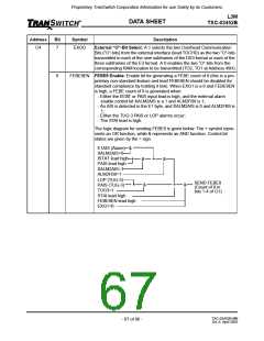
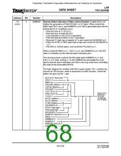
RAMRDI Remote Defect Indication (Yellow alarm) Enabled: Enable bit for con-
trolling the generation of Path RDI (bit 5 in G1 byte). When control bits
RING and EXG1 are 0, and RAMRDI is a 0, RDI is generated when the fol-
lowing alarms or conditions occur:
- Drop bus loss of J1 (DLOJ1)
- Drop bus loss of clock (DLOC)
- Loss of pointer (LOP) (TUG-3 operation)
- Path AIS detected (PAIS) (TUG-3 operation)
- Received E1 byte has a majority of 1s and control bit XALM2AIS is 0
- Either the ISTAT or PAIS input lead is high and control bit XALM2AIS is
a 1
- PSLERR or C2EQ0 alarm, and control bit PSL2AIS is a 1
When control bit RING is a 1, EXG1 is a 0, and RAMRDI is a 0, the RDI
state is controlled via the external alarm indication port.
The microprocessor controls the RDI state when RAMRDI is a 1 and
EXG1 is a 0. Note: writing a 1 to the RAMRDI bit will disable the local
alarms and the alarm indication port RDI in the ring mode from controlling
the state of the transmitted RDI bit.
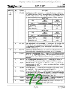
The logic diagram for sending Path RDI is given below. The + symbol rep-
resents an OR function, while & represents an AND function. Control bit
states are given by the = sign.
bit 5 of G1 from port
EXG1=1
RING=0
&
&
PSLERR (Alarm)
C2EQ0 (Alarm)
PSL2AIS=1
LOP (TUG-3)
PAIS (TUG-3)
TUG3=1
+
+
&
SEND PATH
RDI/FERF/
YELLOW
ALARM (Bit
5 in G1 Byte)
+
&
+
&
+
&
+
DLOJ1 (Alarm)
DLOC (Alarm)
E1AIS (Alarm)
XALM2AIS=0
ISTAT lead high
PAIS lead high
XALM2AIS=1
REMOTE ALM I/O
RING=1
&
+
&
&
RAMRDI=0
RAMRDI=1
RAM RDI VALUE
EXG1=0
&
TXC-03452B-MB
Ed. 6, April 2001
- 68 of 96 -

 ETC [ ETC ]