Proprietary TranSwitch Corporation Information for use Solely by its Customers
L3M
TXC-03452B
DATA SHEET
Address
Bit
Symbol
Description
C1
(cont.)
0
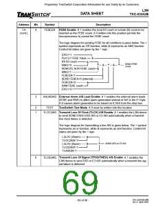
SLBK
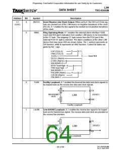
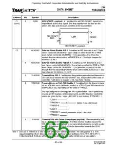
SDH/SONET Loopback: A 1 enables the add SDH/SONET signal to be
looped back as the drop signal. The drop signals from the bus are dis-
abled. Add data and clock are provided at the bus interface.
A
TX
SDH/SONET
L3M
DS3/E3
RX
BUS
D
SDH/SONET Loopback
C2
7
6
ALM2AIS External Alarm Enable AIS: A 1 enables an AIS detected in an E1 byte
(when control bit XALM2AIS = 0) or a high on either the ISTAT or PAIS
leads (when control bit XALM2AIS = 1) to generate a line AIS in the
receive direction when control bit RAISEN is a 1. See logic diagram for
Address C5, bit 2.
ALM2FB9 External Alarm Enable FEBE9: A 1 enables an AIS detected in an E1
byte (when control bit XALM2AIS = 0) or a high on either the ISTAT or PAIS
leads (when control bit XALM2AIS = 1) to generate a count of 9 in bits 1
through 4 of the transmitted G1 byte when control bit FEBE9EN is a 1. See
logic diagram for Address C4, bit 6.
5
4
TLAISGN Transmit Line AIS: A 1 written into this position generates and transmits a
DS3 or E3 AIS towards the SDH/SONET bus, independent of the state of
control bit FLBK (bit 2 in register C1H). See Note 1 below.
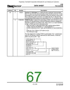
TPAISGN Transmit Zeros or Path AIS Enable: A 1 enables the L3M device to trans-
mit an SPE with zeros (and valid pointer) or a TUG-3 path AIS towards the
SDH/SONET bus, depending on the state of TPAIS00.
The logic diagram for sending path AIS is given below. The + symbol rep-
resents an OR function, while & represents an AND function. Control bit
states are given by the = sign. UNEQUIP is sent instead if TPAIS00 = 1.
TUG3=1
TPAISGN=1
TPAIS00=0
&
&
SEND TUG-3 PATH AIS
SEND UNEQUIP
TUG3=1
TPAISGN=1
TPAIS00=1
3
TPAIS00
Transmit SPE with Zeros (Unequipped payload): When enabled by writ-
ing a 1 to control bit TPAISGN, a 1 written into this location causes the
SPE (POH bytes and payload) to be transmitted with zeros, but with a valid
pointer. A 0 causes a TUG-3 AIS to be transmitted towards the SDH/
SONET bus.
Note 1: DS3 AIS is defined as a valid M-frame with proper subframe structure. The data payload is a 1010...
sequence starting with a 1 after each overhead bit. Overhead bits are as follows: F0=0, F1=1, M0=0, M1=1;
C-bits are set to 0; X-bits are set to 1; and P-bits are set for valid parity. E3 AIS is an all ones pattern.
TXC-03452B-MB
Ed. 6, April 2001
- 65 of 96 -

 ETC [ ETC ]