Proprietary TranSwitch Corporation Information for use Solely by its Customers
L3M
TXC-03452B
DATA SHEET
Address
Bit
Symbol
Description
C4
7
EXOO
External “O”-Bit Select: A 1 selects the two Overhead Communication
Bits (“O”-bits) from the external interface (lead TOCHD) as the two “O”-bits
transmitted in each of the nine subframes of the DS3 format or each of the
three subframes of the E3 format. A 0 enables the two “O”-bits from the
corresponding RAM location to be transmitted (TO2, TO1 at Address 49H).
6
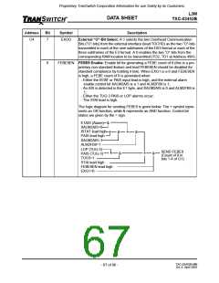
FEBE9EN FEBE9 Enable: Enable bit for generating a FEBE count of 9 (this is a pro-
prietary non-standard feature and lead FEBE9EN should be disabled for
standard compliance by holding it low). When EXG1 is a 0 and FEBE9EN
is high, a FEBE count of 9 is generated when:
- Either the ISTAT or PAIS input lead is high, and the external alarm
enable control bit XALM2AIS is a 1 and ALM2FB9 is 1;
- An AIS is detected in the E1 byte, and XALM2AIS is 0 and ALM2FB9 is
1;
- Either the TUG-3 PAIS or LOP alarms occur;
- The STAI lead is high.
The logic diagram for sending FEBE9 is given below. The + symbol repre-
sents an OR function, while & represents an AND function. Control bit
states are given by the = sign.
E1AIS (Alarm) &
XALM2AIS=0
ISTAT lead high
PAIS lead high
XALM2AIS=1
ALM2FB9=1
LOP (TUG-3)
PAIS (TUG-3)
TUG3=1
+
&
+
&
SEND FEBE9
(Count of 9 in
bits 1-4 of G1)
+
&
+
&
STAI lead high
FEBE9EN lead high
EXG1=0
TXC-03452B-MB
Ed. 6, April 2001
- 67 of 96 -

 ETC [ ETC ]