PCT2303N DATA SHEET
FUNCTIONAL DESCRIPTION
!!
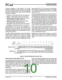
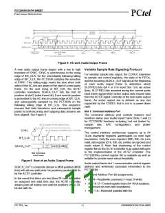
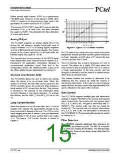
Figure 5 AC-Link Audio Output Frame
A new audio output frame begins with a low to high
transition of SYNC. SYNC is synchronous to the rising
edge of BIT_CLK. On the immediately following falling
edge of BIT_CLK, the PCT303A samples the assertion
of SYNC. This falling edge marks the time when both
sides of the AC-link are aware of the start of a new audio
frame. On the next rising of BIT_CLK, the AC’97
controller transitions SDATA_OUT into the first bit
position of slot 0 (valid frame bit). Each new bit position
is presented to the AC-link on a rising edge of BIT_CLK,
and subsequently sampled by the PCT303A on the
following falling edge of BIT_CLK. This sequence
ensures that data transitions and subsequent sample
points for both incoming and outgoing data streams are
time aligned. See Figure 6.
Variable Sample Rate Signaling Protocol
For variable sample rate output, the CODEC examines
its sample rate control registers, the state of its FIFOs,
and the incoming SDATA_OUT tag bits at the beginning
of each audio output frame to determine which
SLOTREQ bits (bit 4 or 9 in Input Slot 1) to set active
(low). SLOTREQ bits asserted during the current audio
input frame signal which active output slots require data
from the AC’97 Digital Controller in the next audio output
frame. An active output slot is defined as any slot
supported by the CODEC that is not in a power-down
state.
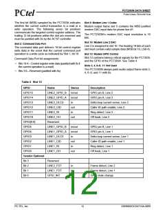
Slot 1: Command Address Port
The command address port controls features and
monitors status (see Audio Input Frame Slots 1 and 2)
for PCT2303N functions including, but not limited to,
sample rate, AFE configuration, and power
management.
The control interface architecture supports up to 64
16-bit read/write registers addressable on even byte
boundaries. Only the even registers (00h, 02h, etc.) are
valid; odd register (01h, 03h, etc.) writes are ignored and
reads return 0. Note that shadowing of the control
register file on the AC’97 controller is an option left open
to the implementation of the AC’97 controller. The
PCT2303N’s control register file is readable as well as
writable to provide more robust testability.
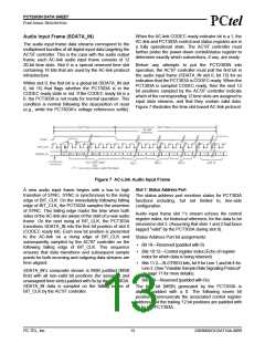
Figure 6 Start of an Audio Output Frame
Audio output frame slot 1 communicates control register
address and write/read command information to the
PCT2303N.
SDATA_OUT’s composite stream is MSB justified (MSB
first) with all non-valid slots’ bit positions padded with 0s
by the AC’97 controller.
Command Address Port bit assignments:
In the event that there are less than 20 valid bits within
an assigned and valid time slot, the AC’97 controller
always pads all trailing non-valid bit positions of the 20-
bit slot with 0s.
• Bit 19—Read/write command (1=read, 0=write)
• Bits 18:12—Control register index (64 16-bit locations,
addressed on even byte boundaries)
• Bits 11:0—Reserved (padded with 0s)
PC-TEL, Inc.
11
2303N0DOCDAT10A-0899

 ETC [ ETC ]