PCT2303N DATA SHEET
FUNCTIONAL DESCRIPTION
!!
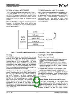
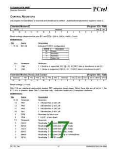
When the AC-link CODEC ready indicator bit is a 1, the
AC-link and PCT303A control and status registers are in
a fully operational state. The AC’97 controller must
further probe the power-down control/status register to
determine exactly which subsections, if any, are ready.
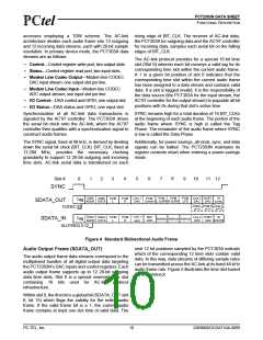
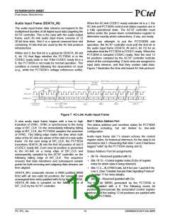
Audio Input Frame (SDATA_IN)
The audio input frame data streams correspond to the
multiplexed bundles of all digital input data targeting the
AC’97 controller. This is the case with the audio output
frame; each AC-link audio input frame consists of 12
20-bit time slots. Slot 0 is a special reserved time slot Before any attempts to put the PCT2303N into
containing 16 bits that are used by the AC-link protocol operation, the AC’97 controller must poll the first bit in
infrastructure.
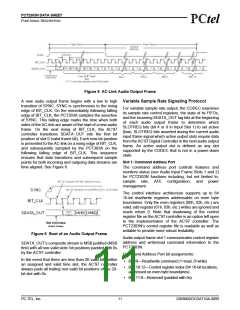
the audio input frame (SDATA_IN slot 0, bit 15) for an
indication that the PCT303A is CODEC ready. When the
PCT303A is sampled CODEC ready, then the next 12
bit positions sampled by the AC’97 controller indicate
which of the corresponding 12 time slots are assigned to
input data streams, and that they contain valid data.
Figure 7 illustrates the time slot-based AC-link protocol.
Within slot 0, the first bit is a global bit (SDATA_IN slot
0, bit 15) that flags whether the PCT303A is in the
CODEC ready state or not. If the CODEC ready bit is a
0, the PCT303A is not ready for normal operation. This
condition is normal following the deassertion of reset
(e.g., while the PCT303A’s voltage references settle).
Figure 7 AC-Link Audio Input Frame
Slot 1: Status Address Port
A new audio input frame begins with a low to high
transition of SYNC. SYNC is synchronous to the rising
edge of BIT_CLK. On the immediately following falling
edge of BIT_CLK, the PCT303A samples the assertion
of SYNC. This falling edge marks the time when both
sides of the AC-link are aware of the start of a new audio
frame. On the next rising of BIT_CLK, the PCT303A
transitions SDATA_IN into the first bit position of slot 0
(CODEC ready bit). Each new bit position is presented
to the AC-link on a rising edge of BIT_CLK and
subsequently sampled by the AC’97 controller on the
following falling edge of BIT_CLK. This sequence
ensures that data transitions and subsequent sample
points for both incoming and outgoing data streams are
time aligned.
The status address port monitors status for PCT303A
functions including, but not limited to, line-side
configuration.
Audio input frame slot 1’s stream echoes the control
register index, for historical reference, for the data to be
returned in slot 2. (Assuming that slots 1 and 2 had been
tagged “valid” by the PCT303A during slot 0).
Status Address Port bit assignments:
• Bit 19—Reserved (padded with 0)
• Bits 18:12—Control register index (Echo of register
index for which data is being returned)
• Bits 11:2—SLOTREQ bits, bit 9 for Line 1 and bit 4 for
Line 2. (See “Variable Sample Rate Signaling Protocol”
on page 11 for more details).
SDATA_IN’s composite stream is MSB justified (MSB
first) with all non-valid bit positions (for assigned and
unassigned time slots) padded with 0s by the PCT303A.
SDATA_IN data is sampled on the falling edges of
BIT_CLK by the AC’97 controller.
• Bits 1:0—Reserved (padded with 0s)
The first bit (MSB) generated by the PCT303A is
always padded with a 0. The following seven bit
positions communicate the associated control register
address and the trailing 12 bit positions are padded with
0s by the PCT303A.
PC-TEL, Inc.
13
2303N0DOCDAT10A-0899

 ETC [ ETC ]