PCT2303N DATA SHEET
FUNCTIONAL DESCRIPTION
!!
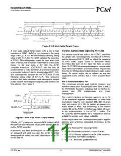
Within normal audio frames, SYNC is a synchronous
PCT303A input. However, in the absence of BIT_CLK,
SYNC is treated as an asynchronous input used in the
generation of a warm reset to the PCT2303N.
15
10
The primary AC’97 CODEC does NOT respond with the
activation of BIT_CLK until SYNC has been sampled
low again by AC’97. This precludes the false detection
of a new audio frame.
LCS
BIT
5
0
Analog Output
0
6
12 18 24 30 36 42 48 54 60 66 72 78 84 90 96
Loop Current (mA)
140
The PCT303A supports an analog output (AOUT) for
driving the call progress speaker found with most of
today’s modems. AOUT is an analog signal comprised
of a mix of the transmit and receive signals. The receive
portion of this mixed signal has a 0 dB gain while the
transmit signal has a gain of –20 dB.
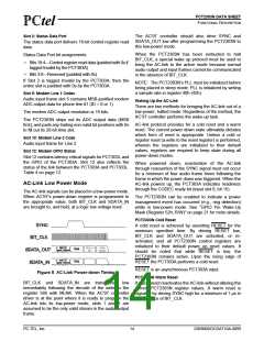
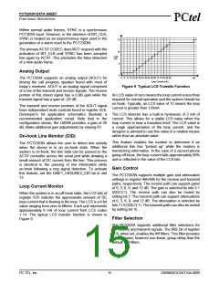
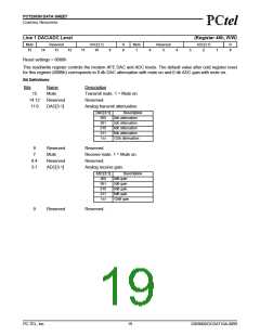
Figure 9 Typical LCS Transfer Function
An LCS value of zero means the loop current is less than
required for normal operation and the system should be
on-hook. Typically, an LCS value of 15 means the loop
current is greater than 120mA.
The transmit and receive portions of the AOUT signal
have independent mute controls found in register 5Ch.
Developer’s kit application schematics illustrate a
recommended application circuit. Note that in the
configuration shown, the LM386 provides a gain of 26
dB. Make additional gain adjustments by varying R1.
The LCS detector has a built-in hysteresis of 2 mA of
current. This allows for a stable LCS value when the
loop current is near a transition level. The LCS value is
a rough approximation of the loop current, and the
designer is advised to use this value in a relative means
rather than an absolute value.
On-hook Line Monitor (CID)
This feature enables the modem to determine if an
additional line has “picked up” while the modem is
transferring information. In the case of a second phone
going off-hook, the loop current falls approximately 50%
and is reflected in the value of the LCS bits.
The PCT2303N allows the user to detect line activity
when the device is in an on-hook state. When the
system is on-hook, the line data can be passed to the
AC’97 controller across the serial port while drawing a
small amount of DC current from the line. This process
is identical to the passing of line information while
on-hook following a ring signal detection. To activate
this feature, set the LINE1_CID/LINE2_CID bit in slot
12.
Gain Control
The PCT2303N supports multiple gain and attenuation
settings in register 46h/48h for the receive and transmit
paths, respectively. The receive path can support gains
of 0, 3, 6, 9, and 12 dB. The gain is selected by bits 3:1
(ADC3:1). The receive path can also be muted by
setting bit 7. The transmit path can support attenuations
of 0, 3, 6, 9, and 12 dB. The attenuation is selected by
bits 11:9 (DAC3:1). The transmit path can also be muted
by setting bit 15.
Loop Current Monitor
When the system is in an off-hook state, the LCS bits of
register 5Ch indicate the approximate amount of DC
loop current that is flowing in the loop. The LCS is a 4-bit
value ranging from zero to fifteen. Each unit represents
approximately 6 mA of loop current from LCS codes
1-14. The typical LCS transfer function is shown in
Figure 9.
Filter Selection
The PCT303A supports additional filter selections for
the receive and transmit signals. The IIRE bit of register
5Ch, when set, enables the IIR filters. This filter provides
a much lower, however non-linear, group delay than the
default FIR filters.
PC-TEL, Inc.
15
2303N0DOCDAT10A-0899

 ETC [ ETC ]