PCT2303N DATA SHEET
FUNCTIONAL DESCRIPTION
!!
accesses employing a TDM scheme. The AC-link rising edge of BIT_CLK. The receiver of AC-link data,
architecture divides each audio frame into 12 outgoing the PCT303A for outgoing data and the AC’97 controller
and 12 incoming data streams, each with 20-bit sample for incoming data, samples each serial bit on the falling
resolution. In primary device mode, the PCT303A data edges of BIT_CLK.
streams are as follows:
The AC-link protocol provides for a special 16-bit time
• Control—Control register write port; two output slots.
• Status—Control register read port; two input slots.
slot (Slot 0) wherein each bit conveys a valid tag for its
corresponding time slot within the current audio frame.
A 1 in a given bit position of slot 0 indicates that the
corresponding time slot within the current audio frame
has been assigned to a data stream and contains valid
data. If a slot is tagged invalid, it is the responsibility of
the data source (the PCT303A for the input stream, the
AC’97 controller for the output stream) to populate all bit
positions with 0s during that slot’s active time.
• Modem Line Codec Output—Modem line CODEC
DAC input stream; one output slot per line.
• Modem Line Codec Input—Modem line CODEC
ADC output stream; one input slot per line.
• I/O Control—DAA control and GPIO; one output slot.
• I/O Status—DAA status and GPIO; one input slot.
Synchronization of all AC-link data transactions is SYNC remains high for a total duration of 16 BIT_CLKs
signaled by the AC’97 controller. The PCT303A drives at the beginning of each audio frame. The portion of the
the serial bit clock onto the AC-link, which the AC’97 audio frame where SYNC is high is called the Tag
controller then qualifies with a synchronization signal to Phase. The remainder of the audio frame where SYNC
construct audio frames.
is low is called the Data Phase.
The SYNC signal, fixed at 48 kHz, is derived by dividing Additionally, for power savings, all clock, sync, and data
down the serial bit clock (BIT_CLK). BIT_CLK, fixed at signals can be halted. The PCT2303N maintains its
12.288 MHz, provides the necessary clocking register contents intact when entering a power-savings
granularity to support 12 20-bit outgoing and incoming mode.
time slots. AC-link serial data is transitioned on each
8
Slot #
0
1
2
3
4
5
6
7
9
10
11 12
SYNC
Line 2
DAC
CMD
Line 1
DAC
PCM
PCM
PCM
HSET
DAC
IO
CTRL
CMD
PCM
L
PCM
R
PCM
Tag
Tag
SDATA_OUT
DATA
Center
ADDR
L SURR R SURR LFE
PCM L PCM R
(n+1) (n+1) (n+1)
PCM C
CODEC ID
Status Status PCM
ADDR DATA
PCM
R
Line 1
ADC
MIC
ADC
Line 2 HSET
ADC ADC STATUS
IO
SDATA_IN
RSRVD RSRVD RSRVD
L
SLOTREQ 3-12
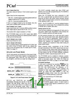
Figure 4 Standard Bidirectional Audio Frame
next 12 bit positions sampled by the PCT303A indicate
which of the corresponding 12 time slots contain valid
data. In this way, data streams of differing sample rates
can be transmitted across the AC-link at its fixed 48-kHz
audio frame rate. Figure 5 illustrates the time slot-based
AC-link protocol.
Audio Output Frame (SDATA_OUT)
The audio output frame data streams correspond to the
multiplexed bundles of all digital output data targeting
the PCT2303N’s DAC inputs and control registers. Each
audio output frame supports up to 12 20-bit outgoing
data time slots. Slot 0 is a special reserved time slot
containing 16 bits used for AC-link protocol
infrastructure.
Within slot 0, the first bit is a global bit (SDATA_OUT slot
0, bit 15) which flags the validity for the entire audio
frame. If the valid frame bit is a 1, the current audio
frame contains at least one slot time of valid data. The
PC-TEL, Inc.
10
2303N0DOCDAT10A-0899

 ETC [ ETC ]