PCT2303N DATA SHEET
FUNCTIONAL DESCRIPTION
!!
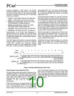
Slot 2: Status Data Port
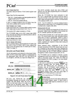
The AC’97 controller should also drive SYNC and
SDATA_OUT low after programming the PCT2303N to
this low-power mode.
The status data port delivers 16-bit control register read
data.
When the PCT2303N has been instructed to halt
BIT_CLK, a special wake up protocol must be used to
bring the AC-link to the active mode because normal
audio output and input frames cannot be communicated
in the absence of BIT_CLK.
Status Data Port bit assignments:
• Bits 19:4—Control register read data (padded with 0s if
tagged Invalid by the PCT303A)
• Bits 3:0—Reserved (padded with 0s)
If Slot 2 is tagged Invalid by the PCT303A, then the
entire slot is padded with 0s by the PCT303A.
NOTE: The PCT2303N’s PLL must be initialized before
being placed in sleep mode. PLL is initialized by writing
a sample rate in register 40h (42h).
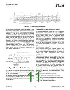
Slot 5: Modem Line 1 Codec
Audio input frame slot 5 contains MSB-justified modem
ADC output data for phone line #1 (ID = 0 or 1).
Waking Up the AC-Link
There are two methods for bringing the AC-link out of a
low-power, halted mode. Regardless of the method, the
AC’97 controller performs the wake-up task.
The modem ADC output resolution is 16 bits.
The PCT2303N ships out its ADC output data (MSB
first), and pads any trailing non-valid bit positions with 0s
to fill out its 20-bit time slot.
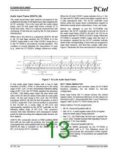
AC-link protocol provides for a cold reset and a warm
reset. The current power down state ultimately dictates
which form of reset is appropriate. Unless a cold or
register reset (a write to the reset register) is performed,
wherein the registers are initialized to their default
values, registers are required to keep state during all
power-down modes.
Slot 10: Modem Line 2 Code
Audio input frame for Line 2.
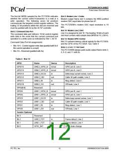
Slot 12: Modem GPIO Status
Slot 12 contains latency critical signals for PCT303L and
the GPIO of the PCT303A. Slot 12 also reflects the
status of the link between the PCT303A and PCT303L.
Table 4 on page 12.
When powered down, reactivation of the AC-link
through reassertion of the SYNC signal must not occur
for a minimum of four audio frame times following the
frame in which the power down was triggered. When the
AC-link powers up, the PCT303A indicates readiness
through the CODEC ready bit (input slot 0, bit 15).
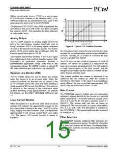
AC-Link Low Power Mode
The AC-link signals can be placed in a low-power mode.
When AC’97’s power-down register is programmed to
the appropriate value, both BIT_CLK and SDATA_IN
are brought to, and held, at a logic low voltage level.
The PCT2303N can be enabled to indicate a power
management event has occurred (e.g., ring detection)
while in low-power mode. See “GPIO Pin Wake-Up
Mask (Register 52h, R/W)” on page 21 for more details.
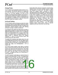
PCT2303N Cold Reset
A cold reset is achieved by asserting RESET for the
minimum specified time. By driving RESET low,
BIT_CLK and SDATA_OUT are activated, or re-
activated, and all PCT2303N control registers are
initialized to their default power on reset values. It
should be noted that while RESET is low, the
PCT2303N remains active. Upon the rising edge of
RESET the PCT303A performs a cold reset.
RESET is an asynchronous PCT303A input.
Figure 8 AC-Link Power-down Timing
PCT2303N Warm Reset
BIT_CLK and SDATA_IN are transitioned low
immediately following the decode of the write to the
register 56h with MLNK. When the AC’97 controller
driver is at the point where it is ready to program the
AC-link into its low-power mode, slots 1 and 2 are
assumed to be the only valid stream in the audio output
frame.
A warm reset reactivates the AC-link without altering the
current PCT2303N register values. A warm reset is
signaled by driving SYNC high for a minimum of 1 µs in
the absence of BIT_CLK.
PC-TEL, Inc.
14
2303N0DOCDAT10A-0899

 ETC [ ETC ]