PCT2303N DATA SHEET
PIN DESCRIPTIONS
!!
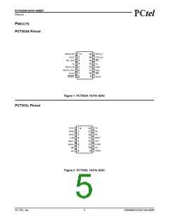
PCT303L Pin Descriptions
Table 2 PCT303L Pin Descriptions
Name
Number I/O Description
Line Interface
TX
16
O
I
Transmit output. Provides the output, through an AC termination impedance, to the
telephone network.
RX
14
12
13
5
Receive input. Serves as the receive side input from the telephone network.
DC termination. Provides DC termination to the telephone network.
External resistor. Connects to an external resistor.
DCT
REXT
RNG1
I
I
Ring 1 input. Connects through a capacitor to the “Tip” lead of the telephone line. Pro-
vides the ring and caller ID signals to the PCT2303N.
RNG2
6
Ring 2 input. Connects through a capacitor to the “Ring” lead of the telephone line. Pro-
vides the ring and caller ID signals to the PCT2303N.
QB
7
8
Transistor base. Connects to the base of the hookswitch transistor.
Transistor emitter. Connects to the emitter of the hookswitch transistor.
QE
HYBD
11
O
Hybrid node output. Balancing capacitor connection used for JATE out-of-band noise
support.
Isolation
C1B
4
3
Isolation capacitor 1B. Connects to one side of isolation capacitor C1.
IGND
Isolated ground. Connects to ground on the line-side interface. Also connects to capac-
itor C2.
Miscellaneous Signals
VREG
TSTA
TSTB
NC
9
Voltage regulator. Connects to an external capacitor to provide bypassing for an inter-
nal voltage regulator.
1
I
I
Test input A. Allows access to test modes, which are reserved for factory use. This pin
has an internal pull-up and should be left as a no-connect for normal operation.
2
Test input B. Allows access to test modes, which are reserved for factory use. This pin
has an internal pull-up and should be left as a no-connect for normal operation.
10,15
No connection. This is an unused pin and must be left floating.
PC-TEL, Inc.
7
2303N0DOCDAT10A-0899

 ETC [ ETC ]