PCT2303N DATA SHEET
FUNCTIONAL DESCRIPTION
!!
PCT303A as Primary MC’97 CODEC
PCT303A Connection to AC’97 Controller
The PCT2303N can operate as a primary AC’97 Rev 2.1 The PCT303A communicates with its companion AC’97
compatible CODEC. However, when there is an audio controller through a digital serial link called the AC-link.
AC’97 CODEC present on the AC-link, the PCT2303N All digital audio streams, optional modem line CODEC
should be configured as a secondary CODEC, and the streams,
and
command/status
information
is
audio AC’97 CODEC should be configured as the communicated over this point to point serial
primary.
interconnect. Figure 3 illustrates the breakout of the
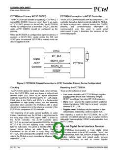
connecting signals.
When the PCT303A is configured as a primary device, it
requires a 24.576 MHz crystal across the XIN and
XOUT pins. An external 24.576 MHz master clock can
also be applied to XIN.
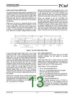
SYNC
BIT_CLK
SDATA_OUT
SDATA_IN
RESET
Digital
AC’97
PCT303A
Controller
Figure 3 PCT2303N Chipset Connection to AC’97 Controller (Primary Device Configuration)
Clocking
Resetting the PCT2303N
The PCT303A derives its internal clock, when primary, There are three types of reset:
from the 24.576 MHz clock and drives a buffered and
• Cold reset—Initializes all PCT2303N logic (registers
divided down (1/2) clock to its digital companion
controller over the AC-link through the BIT_CLK signal.
Clock jitter at the DACs and ADCs is a fundamental
impediment to high quality output, and the internally
generated clock provides the PCT303A with a clean
clock that is independent of the physical proximity of the
PCT303A’s companion AC’97 controller.
included) to its default state. Initiated by bringing
RESET low at least 1 µs when BIT_CLK is inactive.
• Warm reset—Leaves the register contents unaltered.
Initiated by bringing SYNC high for at least 1 µs in the
absence of BIT_CLK.
• Register reset—Initializes only the registers to their
default states. Initiated by a write to register 3Ch.
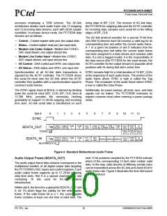
The beginning of all audio sample packets, or audio
frames, transferred over the AC-link is synchronized to
the rising edge of the SYNC signal. SYNC is driven by
the AC’97 controller. The AC’97 controller takes
BIT_CLK as an input and generates SYNC by dividing
BIT_CLK by 256 and applying some conditioning to
tailor its duty cycle. This yields a 48-kHz SYNC signal
whose period defines an audio frame. Data is
transitioned on the AC-link on each rising edge of
BIT_CLK, and subsequently sampled on the receiving
side of the AC-link on each immediately following falling
edge of BIT_CLK.
After signaling a reset to the PCT2303N, the AC’97
controller should not attempt to play or capture modem
data until it has sampled a CODEC ready indication from
the PCT2303N.
AC-Link Digital Serial Interface Protocol
The PCT303A incorporates a 5-pin digital serial
interface that links it to the AC’97 controller. The AC-link
is a bidirectional, fixed rate, serial PCM digital stream. It
handles multiple input and output audio streams
(including modems), as well as control register
PC-TEL, Inc.
9
2303N0DOCDAT10A-0899

 ETC [ ETC ]