PCT2303N DATA SHEET
FUNCTIONAL DESCRIPTION
!!
FUNCTIONAL DESCRIPTION
The PCT2303N is an integrated chipset that provides a
low-cost, isolated, silicon-based MC97-compliant
interface to the telephone line. The PCT2303N saves
cost and board area by eliminating the need for a
modem AFE or serial CODEC. It also eliminates the
need for an isolation transformer, relays, opto-isolators,
and a 2- to 4-wire hybrid. The PCT2303N solution
complies with AC’97/MC’97 Interface specification Rev.
2.1. See AC-Link
Ring Detect
The ring signal enters the PCT303L through low-value
capacitors connected to Tip and Ring.
The integrated ring detect of the PCT2303N allows it to
present the ring signal to the AC’97 controller through
the serial port with no additional signaling required. The
signal sent to the AC’97 controller is a clipped version of
the original ring signal.
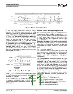
AC-link is a bidirectional, fixed rate, serial PCM digital
stream. It handles multiple input and output audio
streams and control register accesses employing a time
division multiplexed (TDM) scheme. The AC-link
architecture divides each audio frame into 12 outgoing
and 12 incoming data streams, each with 20-bit sample
resolution.
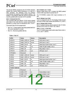
The system can detect a ring occurring by the status of
the RDT bit of slot 12. This bit is a read-only bit that is
set when the line-side device detects a ring signal at
RNG1 and RNG2. When this state occurs, the line-side
chip draws a small amount of DC current from the line to
provide the digitized line data to the AC’97 controller.
This bit clears either when the system goes off-hook or
four to eight seconds after the last ring is detected.
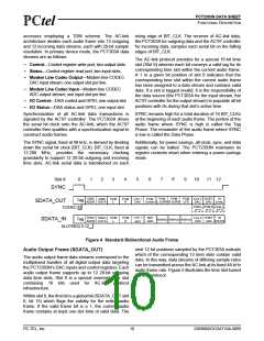
The AC-link serial interconnect defines a digital data and
control pipe between the controller and the CODEC.
The AC-link supports 12 20-bit slots at 48 kHz on
SDATA_IN and SDATA_OUT. The TDM “slot-based”
architecture supports a per-slot valid tag infrastructure
that is the source of each slot’s data sets or clears to
indicate the validity of the slot data within the current
audio frame. For modem AFE, data streams at a variety
of required sample rates can be supported.
Lightning Test
The PCT2303N meets the lightning test requirements of
FCC part 68.
Safety and Isolation
The PCT2303N meets the requirements of FCC part 68
and UL.
Isolation Barrier
Digital Interface
The PCT2303N achieves an isolation barrier through a
low-cost, high-voltage capacitor in conjunction with PC- The ID pins configure the PCT303A as a primary or
TEL’s proprietary signal processing techniques. These secondary AC’97 device as shown in Table 3.
techniques eliminate any signal degradation due to
Table 3 Device ID Configuration
capacitor mismatches, common mode interference, or
noise coupling. All transmit, receive, and control data
are communicated through this barrier.
ID1
1
ID0
1
Description
Primary device
Secondary device #1
Secondary device #2
Factory test
1
0
Off-Hook
0
1
The communication system generates an off-hook
command by writing a logic 1 to bit 0 (line 1) or bit 10
(line 2) of slot 12. The off-hook state is used to seize
the line for an outgoing call and can also be used for
pulse dialing. When the part is not in the off-hook state,
negligible DC current flows through the hookswitch. In
the off-hook state, the hookswitch transistor pair, Q1 &
Q2, turn on.
0
0
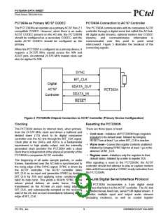
The following sections describe PCT303A operation.
PCT303A as Secondary Device
The PCT303A can operate as a secondary device,
which allows up to two PCT303As to exist on the AC-link
along with a primary device. The primary device can be
an AC’97 Rev. 2.1-compatible CODEC or a PCT303A
configured as the primary device. When configured as a
secondary device, the PCT303A’s BIT_CLK becomes
an input and is used as the master clock. Therefore, XIN
is not used and should be grounded.
PC-TEL, Inc.
8
2303N0DOCDAT10A-0899

 ETC [ ETC ]