Functional Description
AGP accesses in this range are forwarded to PCI. When SMM is enabled the amount of memory
available to the system is equal to the amount of physical DRAM minus the value in the TSEG
register.
Note: When extended SMRAM is used, the maximum amount of DRAM supported is limited to 256 MB.
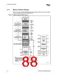
PCI Memory Address Range (Top of Main Memory to 4 GB)
The address range from the top of main DRAM to 4 GB (top of physical memory space supported
by the Intel® 440BX AGPset) is normally mapped to PCI. There are two exceptions to this rule:
• Addresses decoded to the AGP Memory Window defined by the MBASE, MLIMIT,
PMBASE, and PMLIMIT registers are mapped to AGP.
• Addresses decoded to the Graphics Aperture range defined by the APBASE and APSIZE
registers are mapped to the main DRAM.
There are two sub-ranges within the PCI Memory address range defined as APIC Configuration
Space and High BIOS Address Range. The AGP Memory Window and Graphics Aperture Window
MUST NOT overlap with these two ranges. These ranges are described in detail in the following
paragraphs.
APIC Configuration Space (FEC0_0000h -FECF_FFFFh, FEE0_0000h- FEEF_FFFFh)
This range is reserved for APIC configuration space which includes the default I/O APIC
configuration space. The default Local APIC configuration space is FEE0_0000h to FEEF_0FFFh.
CPU accesses to the Local APIC configuration space do not result in external bus activity since the
Local APIC configuration space is internal to the CPU. However, a MTRR must be programmed to
make the Local APIC range uncacheable (UC). The Local APIC base address in each CPU should
be relocated to the FEC0_0000h (4 GB – 20 MB) to FECF_FFFFh range so that one MTRR can be
programmed to 64 KB for the Local and I/O APICs. The I/O APIC(s) usually reside in the I/O
Bridge portion of the AGPset or as a stand-alone component(s). For Intel® 440BX AGPset systems
using the PIIX4E, the I/O APIC is supported as a stand-alone component residing on the X-Bus.
I/O APIC units will be located beginning at the default address FEC0_0000h. The first I/O APIC
will be located at FEC0_0000h. Each I/O APIC unit is located at FEC0_x000h where x is I/O APIC
unit number 0 through F (hex). This address range will be normally mapped to PCI.
Note: There is no provision to support an I/O APIC device on AGP. Also the I/O APIC is not supported in
a mobile platform.
The address range between the APIC configuration space and the High BIOS (FED0_0000h to
FEDF_FFFFh) is always mapped to the PCI.
High BIOS Area (FFE0_0000h –FFFF_FFFFh)
The top 2 MB of the Extended Memory Region is reserved for System BIOS (High BIOS),
extended BIOS for PCI devices, and the A20 alias of the system BIOS. CPU begins execution from
the High BIOS after reset. This region is mapped to PCI so that the upper subset of this region
aliases to 16 MB–256 KB range. The actual address space required for the BIOS is less than 2 MB
but the minimum CPU MTRR range for this region is 2 MB so that full 2 MB must be considered.
The PIIX4E supports a maximum of 1 MB in the High BIOS range.
82443BX Host Bridge Datasheet
4-5

 ETC [ ETC ]