Functional Description
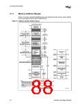
Monochrome Adapter (MDA) Range (B0000h–B7FFFh)
Legacy support requires the ability to have a second graphics controller (monochrome) in the
system. In an AGP system, accesses in the normal VGA range are forwarded to the AGP bus. Since
the monochrome adapter may be on the PCI (or ISA) bus, the 82443BX must decode cycles in the
MDA range and forward them to PCI.
Expansion Area (C0000h–DFFFFh)
This 128 KB ISA Expansion region is divided into eight 16 KB segments. Each segment can be
assigned one of four Read/Write states: read-only, write-only, read/write, or disabled. Typically,
these blocks are mapped through the Host-to-PCI bridge and are subtractively decoded to ISA
space. Memory that is disabled is not remapped.
Extended System BIOS Area (E0000h–EFFFFh)
This 64 KB area is divided into four 16 KB segments. Each segment can be assigned independent
read and write attributes so it can be mapped either to main DRAM or to PCI. Typically, this area is
used for RAM or ROM. Memory segments that are disabled are not remapped elsewhere.
System BIOS Area (F0000h–FFFFFh)
This area is a single 64 KB segment. This segment can be assigned read and write attributes. It is by
default (after reset) Read/Write disabled and cycles are forwarded to PCI. By manipulating the
Read/Write attributes, the 82443BX can “shadow” BIOS into the main DRAM. When disabled,
this segment is not remapped.
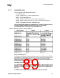
4.1.1.2
Extended Memory Area
This memory area covers 100000h (1 MB) to FFFFFFFFh (4 GB-1) address range and it is divided
into the following regions:
• Main DRAM Memory from 1 MB to the Top of Memory; maximum of 256 MB using 16M
DRAM technology or 1 GB using 64M technology
• PCI Memory space from the Top of Memory to 4 GB with two specific ranges:
— APIC Configuration Space from FEC0_0000h (4 GB-20 MB) to FECF_FFFFh and
EE0_0000h to FEEF_FFFFh
— High BIOS area from 4 GB to 4 GB – 2 MB
Main DRAM Address Range (0010_0000h to Top of Main Memory)
The address range from 1 MB to the top of main memory is mapped to main DRAM address range
controlled by the 82443BX. All accesses to addresses within this range will be forwarded by the
82443BX to the DRAM unless a hole in this range is created using the fixed hole as controlled by
the FDHC register. Accesses within this hole are forwarded to PCI.
The range of physical DRAM memory disabled by opening the hole is not remapped to the Top of
the Memory.
Extended SMRAM Address Range (Top of Main Memory – TSEG)
An extended SMRAM space of up to 1 MB can be defined in the address range at the top of
memory. The size of the SMRAM space is determined by the TSEG value in the ESMRAMC
register. When the extended SMRAM space is enabled, non-SMM CPU accesses and all PCI and
4-4
82443BX Host Bridge Datasheet

 ETC [ ETC ]