ZENTRUM MIKROELEKTRONIK DRESDEN AG
“ASI for you” IC
Datasheet
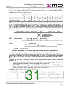
The filter time can be adjusted jointly for all input channels in seven steps by programming the
DI_Filter_Time_Constant register in the Firmware Area of the E²PROM. The following coding table applies:
Table 19: Data Input Filter Time Constants
DI_Filter_Time_Constant, Tolerance = - 6.25%
0
1
2
3
4
5
6
7
128
µs
256
µs
512
µs
1024
µs
2048
µs
4096
µs
8192
µs
AS-i
Corresponding input
filter time constant
cycle
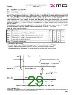
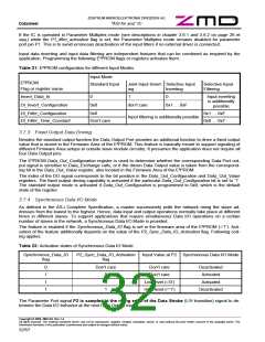
If AS-i cycle mode is selected, a new input value is returned to the master if equal input data was sampled
for two consecutive Data_Exchange cycles. As long as the condition is not true, previous valid data is re-
turned. To suppress undesired input data validation in case of immediately repeated Data_Exchange calls
(i. e. AS-i Masters immediately repeat one Data_Exchange requests if no valid slave response was re-
ceived on the first request) input data sampling is blocked for 256µs (-6.25%) after every sampling event in
AS-i cycle mode.
DEXCHG Addr 1
Slave
DEXCHG Addr1
Slave
DEXCHG Addr 1
Slave
This sampling event is
blocked to avoid immediate
input data validation.
Input
Signal
Filter
Output
< 256 µs (-6.25%)
> 256 µs (-6.25%)
Sampling Point
Figure 13: Principle of AS-i cycle input filtering (exemplary for Slave with Address 1)
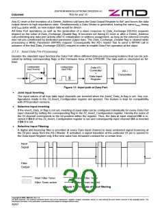
The DI_Filter_Configuration register provides channel selective enabling of input filters; just as the
DI_Invert_Configuration register allows individual inverting of the four Data Port input channels. Again, the
index of the DI channel corresponds to the bit position within the register. Thus, data at input channel DI0 is
filtered if Bit 0 of the DI_Filter_Configuration register is set and consequently input channel DI3 is filtered if
Bit 3 is set.
In general the Data Input Filters become active, as the corresponding bit in the DI_Filter_Configuration
Register is set.
•
They are initialized with ‘0’ and the filter timer is reset after the initialization phase of the IC. (The
first is because an AS-i Master interprets data inputs at ‘0’ to be inactive.)
•
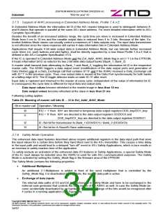
If the P1_Filter_Activation flag is set to ‘1’, the filters will also start to run after the initialization
phase, however the data to construct the slave response is either taken from the actual Data Input
values or the filtered values, depending on the state of Parameter Port P1
Table 20: Input Filter Activation by Parameter Port Pin P1
P1_Filter_Activation Flag
Parameter P1
Data Input Filter Function
ON, active filters depend on DI_Filter_Configuration
OFF
0
1
1
Don’t care
1
0
ON, active filters depend on DI_Filter_Configuration
Copyright © 2006, ZMD AG, Rev.1.4
All rights reserved. The material contained herein may not be reproduced, adapted, merged, translated, stored, or used without the prior written consent of the copyright owner. The
Information furnished in this publication is preliminary and subject to changes without notice.
31/57

 ZMD [ Zentrum Mikroelektronik Dresden AG ]