ZENTRUM MIKROELEKTRONIK DRESDEN AG
“ASI for you” IC
Datasheet
•
Inverter at the data inputs
In Safety Mode it is still possible to use the Data Input Invert functionality (either joint input inverting or
bit selective input inverting) of the IC. This allows to transform the default signal level of the external ap-
plication (either High or Low) to the required default input level for AS-I Safety. For safety considerations
there is no difference whether the inverter is integrated in the ASI4U IC or added externally. An error in
the inverter or inverter activation will be recognized by a running application within the next cycle.
The following feature descriptions relate to the logical signals after the (optional) data input inverters.
Important Note: As described above, the pin assignment of DI2 and DI3 is exchanged in Safety Mode.
However, the configuration register for selective input inverting is directly associated
with the physical IC ports and is not changed. Thus, in Safety Mode Bit3 of the
DI_Invert_Configuration register defines the inverting of the logical signal DI2 and Bit2
defines the inverting the signal DI3.
•
Modification of Code Sequence
The transmitted value for D0 is calculated according to the following equation:
D0 = D0 XOR (D1 AND D2 AND D3)
Thus, the ASI4U will generate ‘1110’ from the input value ‘1111’ and ‘1111’ from the input value ‘1110’.
To comply with the coding rules of the safe AS-i communication, which prohibit ‘1111’ as a valid state in
the data stream, the external code generator has to store ‘1111’ instead of ‘1110’.
In case the Safety Mode became accidentally deactivated by an hardware fault, the IC would not per-
form the D0 combination anymore. The Safety Monitor would notice this as an error by reception of
‘1111’, see Figure 15.
•
•
Deactivation of the standard data path
Theoretically, the Safety Mode could become deactivated for a single bit only, if a (single) fault occurs at
one of the multiplexers. This would lead to code sequences where three bits are routed in the Safety
Path and the fourth bit is routed in the Standard Path. Therefore, an additional OR-Gate is added in the
Standard Path, that ties the Standard Path to constant ‘1’ once the Safety Mode is activated.
A valid data transfer in Standard Mode or Safety Mode is only possible, if all four multiplexers are
switched to the same direction. Any other state will be recognized by the Safety Monitor.
Activation of Data_Exchange_Disable
The Data_Exchange_Disable flag is set by the IC after Reset and will be cleared after the first Parame-
ter call. As long as the flag is set, the IC does not respond to Data_Exchange calls. In case the Safety
Mode is activated and the Synchronous_Data_IO flag or any of the DI_Filter_Configuration flags are set
in the Firmware Area of the E²PROM, the Data_Exchange_Disable flag cannot be cleared. This pre-
vents any data communication in that particular case. See Figure 16.
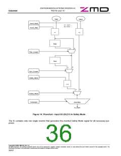
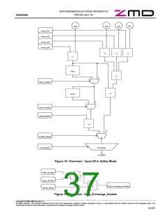
Following flow charts are valid in Safety Mode of the ASI4U:
Note:
>=1 represents a logical OR
=1 represents a logical XOR
& represents a logical AND
Copyright © 2006, ZMD AG, Rev.1.4
All rights reserved. The material contained herein may not be reproduced, adapted, merged, translated, stored, or used without the prior written consent of the copyright owner. The
Information furnished in this publication is preliminary and subject to changes without notice.
35/57

 ZMD [ Zentrum Mikroelektronik Dresden AG ]