ZENTRUM MIKROELEKTRONIK DRESDEN AG
“ASI for you” IC
Datasheet
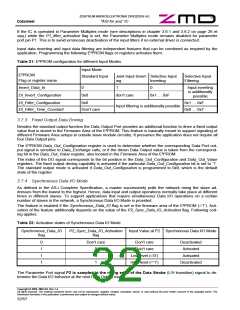
If the IC is operated in Parameter Multiplex mode (see description in chapter 3.6.1 on page 26) while Synchro-
nous_Data_IO flag and P2_Sync_Data_IO_Activation flag are set, the Parameter Multiplex mode remains dis-
abled for parameter port pin P2. This is to avoid erroneous deactivation of the Synchronous Data IO mode in
case no external driver is connected.
Once activated, input data sampling as well as output data driving events are moved to different times syn-
chronized to the polling cycle of the AS-i network. Nevertheless, the communication principles between master
and slave remain unchanged compared to regular operation. Following rules apply:
•
Data I/O is triggered by the DEXG call to slave with the lowest slave address in the network. Based on
the fact, that a master is calling slaves successively with rising slave addresses, the ASI4U considers
the trigger condition true, if the slave address of a received DEXG call is less than the slave address of
the previous (correctly received) DEXG call.
Data I/O is only triggered, if the slave has (correctly) received data during the last cycle. If the slave did
not receive data (i.e. due to a communication error) the Data Outputs are not changed and no Data
Strobe is generated (arm+fire principle). The inputs however, are always sampled at the trigger event.
•
If the slave with the lowest address in the network is operated in the Synchronous Data I/O Mode, it
postpones the output event for the received data for a full AS-i cycle. This is to keep all output data of a
particular cycle image together.
Note: To make this feature useful, the master shall generate a data output cycle image once before the
start of every AS-i cycle. The image is derived from the input data of the previous cycle(s) and other
control events. If an AS-i cycle has started, the image shall not change anymore. In case A- and B-
slaves are installed in parallel at one address, the master shall address all A-Slaves in one cycle and all
B-Slaves in the other cycle.
The input data, sampled at the slave with the lowest slave address in the network, is sent back to the
master without any delay. Thus, the input data cycle image is fully captured at the end of an AS-i cycle,
just as in networks without any Synchronous Data I/O Mode slaves. In other words, the input data sam-
pling point has simply moved to the beginning of the AS-i cycle for all Synchronous Data I/O Mode
slaves.
•
The first DEXG call that is received by a particular slave after the activation of the Data Port
(Data_Exchange_Disable flag was cleared by a WPAR call is processed like in regular operation. This
is to capture decent input data for the first slave response and to activate the outputs as fast as possi-
ble.
The Data I/O operation is repeated together with the I/O cycle of the other Synchronous Data I/O Mode
slaves in the network at the common trigger event. By that, the particular slave has fully reached the
Synchronous Data I/O Mode.
•
•
If the P2_Sync_Data_IO_Activation flag is set to ‘1’ at the slave with the lowest address in the net-
work, one data output value is lost when the Synchronous Data I/O Mode is turned off (L/H transition at
P2), while the value that is received in the cycle when the IC detects a signal change at P2 (H/L transi-
tion) is repeated. This particular behavior is caused by the fact that in Synchronous Data I/O Mode the
data output at the slave with the lowest address is postponed for a full AS-i cycle (see description
above).
To avoid a general suppression of Data I/O in the special case that a slave in Synchronous Data I/O
mode receives DEXG calls only to its own address (i.e. employment of a handheld programming de-
vice), the Synchronous Data I/O Mode is turned off, once the ASI4U receives three consecutive DEXG
calls to its own slave address. The IC resumes to Synchronous Data I/O Mode operation after it ob-
served a DEXG call to a different slave address than its own. The reactivation of the Synchronous Data
I/O mode is handled likewise for the first DEXG call after activation of the Data Port (see description
above).
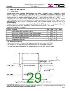
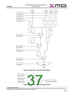
The Data Strobe (DSR) signal is of course also generated in Synchronous Data I/O Mode. The timings of input
sampling and output buffering correspond to the regular operation (refer to Figure 10 and Table 18).
Copyright © 2006, ZMD AG, Rev.1.4
All rights reserved. The material contained herein may not be reproduced, adapted, merged, translated, stored, or used without the prior written consent of the copyright owner. The
Information furnished in this publication is preliminary and subject to changes without notice.
33/57

 ZMD [ Zentrum Mikroelektronik Dresden AG ]