ZENTRUM MIKROELEKTRONIK DRESDEN AG
“ASI for you” IC
Datasheet
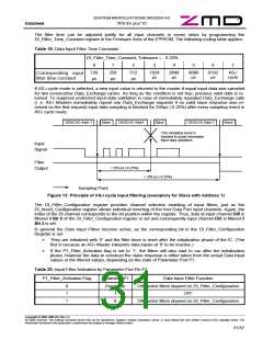
If the IC is operated in Parameter Multiplex mode (see descriptions in chapter 3.6.1 and 3.6.2 on page 26 et
sqq.) while the P1_filter_activation flag is set, the Parameter Multiplex mode remains disabled for parameter
port pin P1. This is to avoid erroneous deactivation of the input filters if no external driver is connected.
Input data inverting and input data filtering are independent features that can be combined as required by the
application. Programming the following E²PROM flags or registers activates them:
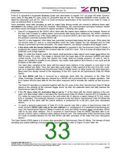
Table 21: E²PROM configuration for different Input Modes
Input Mode
E²PROM
Flag or register name
Standard Input
Joint Input Invert- Selective Input
Selective Input
Filtering
ing
Inverting
0
Invert_Data_In
0
1
Input inverting
is additionally
possible
DI_Invert_Configuration
0x0
don’t care
0x1 … 0xF
DI_Filter_Configuration
DI_Filter_Time_Constant
0x0
0x1 … 0xF
0x0 … 0x7
Input filtering is additionally possible
Don’t care
3.7.3 Fixed Output Data Driving
Besides the standard output function the Data Output Port provides an additional function to drive a fixed output
value that is stored in the Firmware Area of the E²PROM. This feature is basically meant to support signaling of
different Firmware Area setups to outside slave module circuitry. It presumes the application does not require all
four Data Output pins.
The E²PROM Data_Out_Configuration register is used to determine whether the corresponding Data Port out-
put signal is sensitive to Data_Exchange calls, or if the driven Data Output value is taken from the correspond-
ing bit in the Data_Out_Value register, also located in the Firmware Area of the E²PROM.
The index of the DO signal corresponds to the bit position in the Data_Out_Configuration and Data_Out_Value
registers. The fixed output driving capability is activated if the particular Data_Out_Configuration bit is set to ‘1’.
The standard output mode is activated if Data_Out_Configuration is programmed to 0x0, which is the default
state of the register.
3.7.4 Synchronous Data I/O Mode
As defined in the AS-i Complete Specification, a master successively polls the network rising the slave ad-
dresses from the lowest to the highest. Hence, data input and output operations normally take place at different
times in different slaves. To support applications that require simultaneous Data I/O operations on a certain
number of slaves in the network, a Synchronous Data I/O Mode is provided.
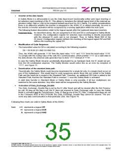
The feature is enabled if the Synchronous_Data_IO flag is set in the firmware area of the E²PROM (=’1’). Acti-
vation of the feature additionally depends on the value of the P2_Sync_Data_IO_Activation flag. Following cod-
ing applies:
Table 22: Activation states of Synchronous Data IO Mode
Synchronous_Data_IO
P2_Sync_Data_IO_Activation
Input Value at P2 Synchronous Data I/O Mode
flag
flag
0
1
1
1
Don’t care
Don’t care
Don’t care
Deactivated
Activated
0
1
1
Low level (=’0’)
High level (=’1’)
Activated
Deactivated
The Parameter Port signal P2 is sampled at the rising edge of the Data Strobe (L/H transition) signal to de-
termine the Data I/O behavior at the next Data Output event.
Copyright © 2006, ZMD AG, Rev.1.4
All rights reserved. The material contained herein may not be reproduced, adapted, merged, translated, stored, or used without the prior written consent of the copyright owner. The
Information furnished in this publication is preliminary and subject to changes without notice.
32/57

 ZMD [ Zentrum Mikroelektronik Dresden AG ]