ZENTRUM MIKROELEKTRONIK DRESDEN AG
“ASI for you” IC
Datasheet
3.7.5 Support of 4I/4O processing in Extended Address Mode, Profile 7.A.x.E
In Extended Address Mode the information bit I3 of the AS-i master telegram is used to distinguish between A-
and B-slaves that operate in parallel at the same AS-i slave address. For more detailed information refer to AS-i
Complete Specification.
Besides the benefit of an increased address range, the cycle time per slave is increased in Extended Address
Mode from 5 ms to 10 ms and the useable output data is reduced from 4 to 3 bits. Because of the later, Ex-
tended Address Mode slaves can usually control a maximum of 3 data outputs only. The input data transmission
is not effected since the slave response still carries 4 data information bits in Extended Address Mode.
Applications that require 4 bit wide output data in Extended Address Mode, but can tolerate further increased
cycle times (i.e. push buttons and pilot lights), shall be directly supported by a new Slave Profile 7.A.x.E that is
defined in the AS-i Complete Specification V3.0.
If the IC is operated in Extended Address Mode and the Ext_Addr_4I/4O_Mode flag is set (=’1’) in the E²PROM,
it treats information bit I2 as selector for two 2-bit wide data output banks (Bank_1, Bank_2).
A master shall transmit data alternating to Bank_1 and Bank_2, toggling the information bit I2 in the respective
master calls. The ASI4U triggers a data output event (modification of the data output ports and generation of
Data Strobe) only at a Data_Exchange call that contains I2=’0’ and if the ASI4U received a Data_Exchange call
with I2=’1’ in the previous cycle. Thus, new output data is issued at the Data Port synchronously for both banks
at a falling edge of I2. The I2 toggle detector starts on state I2=’0’ after reset.
Input data is captured and returned to the master at every cycle, independent of the value of information bit I2.
In consequence the cycle time is different for input data and output data:
-
-
Data input values become refreshed in the master image in less than 10 ms
Data output values become refreshed at the slave in less than 21 ms
Following coding applies:
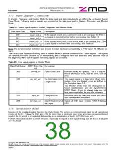
Table 23: Meaning of master call bits I0 … I3 in Ext_Addr_4I/4O_Mode
Bit in master call Operation / Meaning
I0
I1
If I2 = ‘1’ then I0/I1 are directed to temporary data output registers DO0_tmp/DO1_tmp
If I2 = ‘0’ then I0/I1 are directed to the data output registers DO2/DO3 and
DO0_tmp/DO1_tmp are directed to the data output registers DO0/DO1
I2
I3
I2: /Sel-bit for transmission to Bank_1 (DO0/DO1) / Bank_2 (DO2/DO3)
I3: /Sel-bit for A-Slave/B-Slave addressing
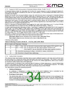
3.7.6 Safety Mode Operation
The enhanced data input features described above require additional registers in the data input path that store
the input values for a certain time before they hand them over to the AS-i transmitter. This causes a time delay
in the input path and would lead to a delayed “turn off” event in AS-i Safety Applications, which in turn results in
an increase in safety reaction time of the application.
To safely exclude an activation of the enhanced data I/O features in Safety Applications, a special Safety Mode
of the IC must always be selected once the ASI4U is used for safe AS-i communication purposes. The Safety
Mode is activated by setting the Safety_Mode flag in the firmware area of the E²PROM.
The Safety Mode contains the following properties:
•
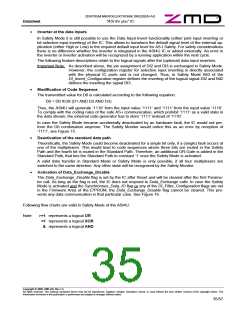
Additional Multiplexer
An additional 2:1-Multiplexer is added in front of the send multiplexer that is controlled by the
Safety_Mode flag. For deactivated Safety Mode, the regular data path is active.
•
Exchange of data inputs
The internal data paths of D3 and D2 are exchanged in Safety Mode and have to be exchanged in the
external code generator that controls the Data Inputs of the ASI4U as well. In case the Safety Mode be-
came accidentally deactivated by an hardware fault, an exchange of the bits would be recognized after
4 cycles in a running application (see Figure 14).
Copyright © 2006, ZMD AG, Rev.1.4
All rights reserved. The material contained herein may not be reproduced, adapted, merged, translated, stored, or used without the prior written consent of the copyright owner. The
Information furnished in this publication is preliminary and subject to changes without notice.
34/57

 ZMD [ Zentrum Mikroelektronik Dresden AG ]