ZENTRUM MIKROELEKTRONIK DRESDEN AG
“ASI for you” IC
Datasheet
3.6.2 Parameter Multiplex Mode
AS-i Complete Specification v3.0 defines a so called Parameter Multiplex Mode. This new feature allows bi-
directional data transfer through the parameter port. The bi-directionality is achieved by turning the Parameter
Output Drivers off after the Parameter Strobe period and before the input sampling event. By turning off its out-
put drivers during the Parameter Strobe pulse, an external microcontroller can read the data from the Parameter
Port of the ASI4U, prepare new return data and place it to the port right after the Parameter Strobe signal.
The Parameter Multiplex Mode becomes activated by setting the corresponding Multiplex_Parameter flag (=’1’)
in the E²PROM.
To keep full compatibility to A²SI based applications this flag should be kept zero (=’0’). The A²SI did not allow
real bi-directional parameter data transfer since it was not able to turn the output drivers off. The return value to
a Write_Parameter call was always a wired AND combination of the output signal of the IC and the signal driven
to the port by the external logic.
3.6.3 Special function of P0, P1 and P2
In case the Watchdog_Active flag is not set (=’0’) but the P0_Watchdog_Activation flag is set (= ‘1’, Firmware
Area of the E²PROM) the value of the Parameter Port signal P0 determines whether the communication watch-
dog is enabled or disabled. In compliance to Slave Profile 7D-5 the behavior is defined as follows:
Input Value at P0
Low level (=’0’)
High level (=’1’)
State of Communication Watchdog
Disabled
Enabled
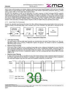
If the P1_Filter_Activation flag is set in the E²PROM, the activation of the data input filters depends on the value
of the Parameter Port signal P1. Following coding applies:
Input Value at P1
Low level (=’0’)
High level (=’1’)
Data input filter function
Activated
Deactivated
For further details refer to chapter 3.7 Data Port and DSR – Input Data Pre-Processing.
If the Synchronous_Data_I/O_Mode flag is set in the E²PROM, the value of the parameter port P2 activates or
deactivates the Synchronous Data I/O Mode of the ASI4U. Following coding applies:
Input Value at P2
Low level (=’0’)
High level (=’1’)
Synchronous Data I/O Mode
Activated
Deactivated
For further details refer to chapter 3.7 Data Port and DSR – Synchronous Data I/O Mode.
The processed values of P0, P1 and P2 result from a wired-AND combination between the corresponding out-
put value and the input value driven by an external signal source.
Copyright © 2006, ZMD AG, Rev.1.4
All rights reserved. The material contained herein may not be reproduced, adapted, merged, translated, stored, or used without the prior written consent of the copyright owner. The
Information furnished in this publication is preliminary and subject to changes without notice.
27/57

 ZMD [ Zentrum Mikroelektronik Dresden AG ]