eZ80L92 MCU
Product Specification
133
Write Collision
The WRITE COLLISION flag, WCOL (SPI_SR[5]), is set to 1 when an attempt is made
to write to the SPI Transmit Shift register (SPI_TSR) while data transfer occurs. Clearing
the WCOL bit is performed by reading SPI_SR with the WCOL bit set.
SPI Baud Rate Generator
The SPI’s Baud Rate Generator creates a lower frequency clock from the high-frequency
system clock. The Baud Rate Generator output is used as the clock source by the SPI.
Baud Rate Generator Functional Description
The SPI’s Baud Rate Generator consists of a 16-bit downcounter, two 8-bit registers, and
associated decoding logic. The Baud Rate Generator’s initial value is defined by the two
BRG Divisor Latch registers, {SPI_BRG_H, SPI_BRG_L}. At the rising edge of each
system clock, the BRG decrements until it reaches the value 0001h. On the next system
clock rising edge, the BRG reloads the initial value from {SPI_BRG_H, SPI_BRG_L) and
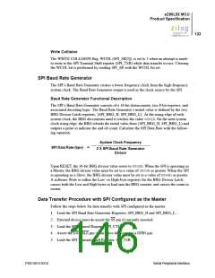
outputs a pulse to indicate the end-of-count. Calculate the SPI Data Rate with the follow-
ing equation:
System Clock Frequency
SPI Data Rate (bps)
=
2 X SPI Baud Rate Generator
Divisor
Upon RESET, the 16-bit BRG divisor value resets to 0002h. When the SPI is operating as
a Master, the BRG divisor value must be set to a value of 0003h or greater. When the SPI
is operating as a Slave, the BRG divisor value must be set to a value of 0004h or greater.
A software Write to either the Low- or High-byte registers for the BRG Divisor Latch
causes both the Low and High bytes to load into the BRG counter, and causes the count to
restart.
Data Transfer Procedure with SPI Configured as the Master
Follow the steps below for data transfer with SPI configured as the master:
1. Load the SPI Baud Rate Generator Registers, SPI_BRG_H and SPI_BRG_L.
2. External device must de-assert the SS pin if currently asserted.
3. Load the SPI Control Register, SPI_CTL.
4. Assert the ENABLE pin of the slave device using a GPIO pin.
5. Load the SPI Transmit Shift Register, SPI_TSR.
PS013015-0316
Serial Peripheral Interface

 ZILOG [ ZILOG, INC. ]