eZ80L92 MCU
Product Specification
134
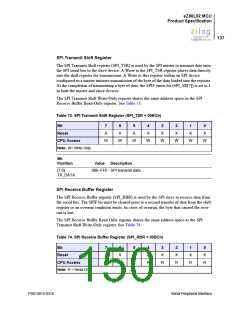
6. When the SPI data transfer is complete, de-assert the ENABLE pin of the slave
device.
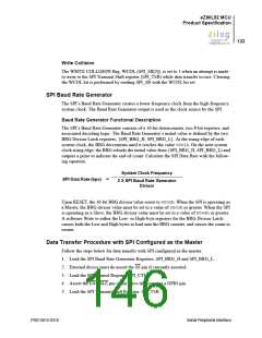
Data Transfer Procedure with SPI Configured as a Slave
Follow the steps below for data transfer with SPI configured as the slave:
1. Load the SPI Baud Rate Generator Registers, SPI_BRG_H and SPI_BRG_L.
2. Load the SPI Transmit Shift Register, SPI_TSR. This load cannot occur while the SPI
slave is currently receiving data.
3. Wait for the external SPI Master device to initiate the data transfer by asserting SS.
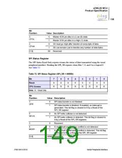
SPI Registers
There are six registers in the Serial Peripheral Interface which provide control, status, and
data storage functions. The SPI registers are described in the following section.
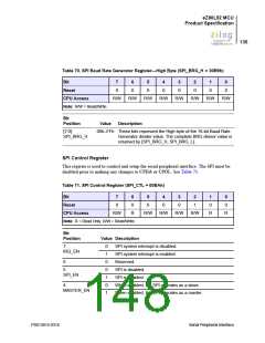
SPI Baud Rate Generator Registers—Low Byte and High Byte
These registers hold the Low and High bytes of the 16-bit divisor count loaded by the
processor for baud rate generation. The 16-bit clock divisor value is returned by
{SPI_BRG_H, SPI_BRG_L}. Upon RESET, the 16-bit BRG divisor value resets to
0002h. When configured as a Master, the 16-bit divisor value must be between 0003h
and FFFFh, inclusive. When configured as a Slave, the 16-bit divisor value must be
between 0004h and FFFFh, inclusive.
A Write to either the Low or High byte registers for the BRG Divisor Latch causes both
bytes to be loaded into the BRG counter and the count restarted. See Table 69 and
Table 70.
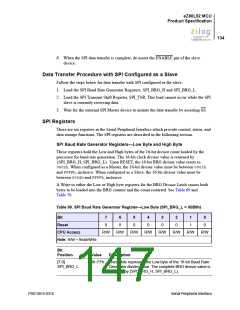
Table 69. SPI Baud Rate Generator Register—Low Byte (SPI_BRG_L = 00B8h)
Bit
7
0
6
0
5
0
4
0
3
0
2
0
1
1
0
0
Reset
CPU Access
Note: R/W = Read/Write.
R/W
R/W
R/W
R/W
R/W
R/W
R/W
R/W
Bit
Position
Value
Description
[7:0]
SPI_BRG_L
00h–FFh These bits represent the Low byte of the 16-bit Baud Rate
Generator divider value. The complete BRG divisor value is
returned by {SPI_BRG_H, SPI_BRG_L}.
PS013015-0316
Serial Peripheral Interface

 ZILOG [ ZILOG, INC. ]