eZ80L92 MCU
Product Specification
129
SPI Signals
The four basic SPI signals are:
•
•
•
•
MISO (Master-In/Slave-Out)
MOSI (Master-Out/Slave-In)
SCK (SPI Serial Clock)
SS (Slave Select)
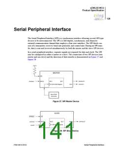
The following section describes the SPI signals. Each signal is described in both
MASTER and SLAVE modes.
Master-In, Slave-Out
The Master-In/Slave-Out (MISO) pin is configured as an input in a master device and as
an output in a slave device. It is one of the two lines that transfer serial data, with the most
significant bit sent first. The MISO pin of a slave device is placed in a high-impedance
state if the slave is not selected. When the SPI is not enabled, this signal is in a high-
impedance state.
Master-Out, Slave-In
The Master-Out/Slave-In (MOSI) pin is configured as an output in a master device and as
an input in a slave device. It is one of the two lines that transfer serial data, with the most
significant bit sent first. When the SPI is not enabled, this signal is in a high-impedance
state.
Slave Select
The active Low Slave Select (SS) input signal is used to select the SPI as a slave device. It
must be Low prior to all data communication and must stay Low for the duration of the
data transfer.
The SS input signal must be High for the SPI to operate as a master device. If the SS signal
goes Low, a Mode Fault error flag (MODF) is set in the SPI_SR register. See the SPI Sta-
tus Register (SPI_SR) on page 136 for more information.
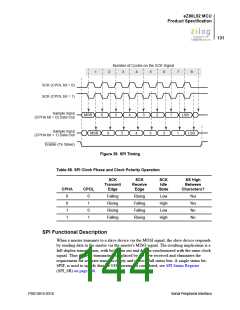
When the clock phase (CPHA) is set to 0, the shift clock is the logical OR of SS with
SCK. In this clock phase mode, SS must go High between successive characters in an SPI
message. When CPHA is set to 1, SS can remain Low for several SPI characters. In cases
where there is only one SPI slave, its SS line could be tied Low as long as CPHA is set to
1. See the SPI Control Register (SPI_CTL) on page 135 for more information about
CPHA.
PS013015-0316
Serial Peripheral Interface

 ZILOG [ ZILOG, INC. ]