eZ80L92 MCU
Product Specification
117
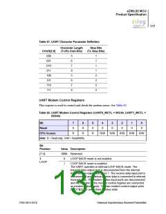
Table 61. UART Character Parameter Definition
Character Length
(Tx/Rx Data Bits)
Stop Bits
(Tx Stop Bits)
CHAR[2:0]
000
5
6
7
8
5
6
7
8
1
1
1
1
2
2
2
2
001
010
011
100
101
110
111
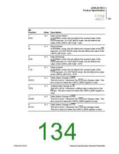
UART Modem Control Registers
This register is used to control and check the modem status. See Table 62.
Table 62. UART Modem Control Registers (UART0_MCTL = 00C4h, UART1_MCTL =
00D4h)
Bit
7
0
6
0
5
0
4
0
3
0
2
0
1
0
0
0
Reset
CPU Access
R
R
R
R/W
R/W
R/W
R/W
R/W
Note: R = Read only.; R/W = Read/Write.
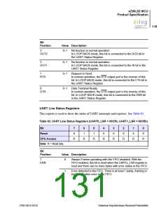
Bit
Position
Value Description
[7:5]
000b Reserved.
4
0
1
LOOP BACK mode is not enabled.
LOOP BACK mode is enabled.
LOOP
The UART operates in internal LOOP BACK mode. The
transmit data output port is disconnected from the internal
transmit data output and set to 1. The receive data input port is
disconnected and internal receive data is connected to internal
transmit data. The modem status input ports are disconnected
and the four bits of the modem control register are connected
as modem status inputs. The two modem control output ports
(OUT1&2) are set to their inactive state
PS013015-0316
Universal Asynchronous Receiver/Transmitter

 ZILOG [ ZILOG, INC. ]