eZ80L92 MCU
Product Specification
118
Bit
Position
Value Description
3
0–1 No function in normal operation.
OUT2
In LOOP BACK mode, this bit is connected to the DCD bit in
the UART Status Register.
2
0–1 No function in normal operation.
In LOOP BACK mode, this bit is connected to the RI bit in the
UART Status Register.
OUT1
1
0–1 Request to Send.
RTS
In normal operation, the RTS output port is the inverse of this
bit. In LOOP BACK mode, this bit is connected to the CTS bit in
the UART Status Register.
0
0–1 Data Terminal Ready.
DTR
In normal operation, the DTR output port is the inverse of this
bit. In LOOP BACK mode, this bit is connected to the DSR bit
in the UART Status Register.
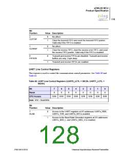
UART Line Status Registers
This register is used to show the status of UART interrupts and registers. See Table 63.
Table 63. UART Line Status Registers (UART0_LSR = 00C5h, UART1_LSR = 00D5h)
Bit
7
0
6
1
5
1
4
0
3
0
2
0
1
0
0
0
Reset
CPU Access
Note: R = Read only.
R
R
R
R
R
R
R
R
Bit
Position
Value Description
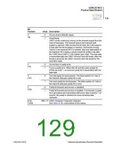
7
0
Always 0 when operating with the FIFO disabled. With the
ERR
FIFO enabled, this bit is reset when the UARTx_LSR register is
read and there are no more bytes with error status in the FIFO.
1
Error detected in the FIFO. There is at least 1 parity, framing or
break indication error in the FIFO.
PS013015-0316
Universal Asynchronous Receiver/Transmitter

 ZILOG [ ZILOG, INC. ]