eZ80L92 MCU
Product Specification
121
Bit
Position
Value Description
7
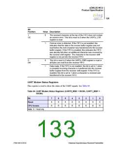
0–1 Data Carrier Detect
DCD
In NORMAL mode, this bit reflects the inverted state of the
DCDx input pin. In LOOP BACK mode, this bit reflects the
value of the UARTx_MCTL[3] = out2.
6
0–1 Ring Indicator
RI
In NORMAL mode, this bit reflects the inverted state of the RIx
input pin. In LOOP BACK mode, this bit reflects the value of the
UARTx_MCTL[2] = out1.
5
0–1 Data Set Ready
DSR
In NORMAL mode, this bit reflects the inverted state of the
DSRx input pin. In LOOP BACK mode, this bit reflects the
value of the UARTx_MCTL[0] = DTR.
4
0–1 Clear to Send
CTS
In NORMAL mode, this bit reflects the inverted state of the
CTSx input pin. In LOOP BACK mode, this bit reflects the value
of the UARTx_MCTL[1] = RTS.
3
0–1 Delta Status Change of DCD
DDCD
This bit is set to 1 whenever the DCDx pin changes state. This
bit is reset to 0 when the UARTx_MSR register is read.
2
0–1 Trailing Edge Change on RI.
TERI
This bit is set to 1 whenever a falling edge is detected on the
RIx pin. This bit is reset to 0 when the UARTx_MSR register is
read.
1
0–1 Delta Status Change of DSR
DDSR
This bit is set to 1 whenever the DSRx pin changes state. This
bit is reset to 0 when the UARTx_MSR register is read.
0
0–1 Delta Status Change of CTS
DCTS
This bit is set to 1 whenever the CTSx pin changes state.
This bit is reset to 0 when the UARTx_MSR register is read.
PS013015-0316
Universal Asynchronous Receiver/Transmitter

 ZILOG [ ZILOG, INC. ]