GP2021
IPS_3V_MODE: When set high this control bit sets the
input buffers on SIGN0, MAG0, SIGN1, and MAG1 for
signals centred on mid-supply, for use with a front end
running from a 3V supply. When low, it sets the thresholds
toTTLlevels for 5V operation. Master reset forces IPS_3V
to low.
The function of the TEST_CONTROL register is purely to
enable various test modes. A master reset (NRESET low)
will set all bits to low, giving normal operation.
EN_DUMMYDUMP: When high, this bit changes the
function of the NOPC/NINTELMOT input pin to be a
DUMMYDUMP input, and if in Standard Interface Mode it
also forces the microprocessor mode to Motorola. A
DUMMYDUMP will operate in the same way as a normal
DUMP (reset all of the code generators and transfer the
contents of all integrators into the Accumulated Data
registers). Each low to high transition of NOPC/
NINTELMOT will cause a DUMMYDUMP and if NOPC/
NINTELMOT is already high when EN_DUMMYDUMP is
set, one will also occur immediately. Selecting Dummy
dump mode does not inhibit normal DUMP events. The
NOPC/NINTELMOT pin must be held high for at least
200 ns for each DUMMYDUMP.
INTERRUPT_PERIOD: When low, the interrupt period is
set to approximately 505µs and when high it is set to 854s.
For more detail see the description of PROG_ACCUM_INT
on page 38. Master reset forces INTERRUPT_PERIOD
bit to low.
FRONT_END_MODE: Selects either Real_lnput mode
when low or Complex_lnput mode when high. Master reset
forces FRONT_END_MODE to low.
INTERRUPT_ENABLE: When set low the effect of the
ACCUM_INT and MEAS_INT interrupts are disabled
(masked) and when set high both are enabled. Master
reset forces INTERRUPT_ENABLE Low.
EN_DUMMYTICS: When High this bit changes the function
of the DISCIP input pin to a DUMMYTIC input. This
replaces the TIC from the timebase generator so that a
TIC effect will only occur when there is a low to high
transition on DISCIP, to latch new Measurement Data. The
DISCIP pin must be held high for at least 200ns for each
DUMMYTIC.
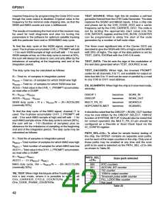
Bits 4 to 1: The signal provided on the DlSCOP pin can
be selected according to Table 26.
Bit
Signal on DISCOP output
4
3
2
1
FE_TEST: When high this test control forces the SIGN
input to channel 11 and the MAG input to channel 5 both
to low. This allows the evaluation of the front end SIGN
(on channel 5) and MAG (on channel 11 ) duty cycles. The
front end to be tested is selected by the SOURCESEL bits
in CH5_SATCNTL and CH11_SATCNTL.To get the SIGN
and MAG count correctly into the accumulators, both the
carrier and code mixers must be made transparent.
0
0
0
0
1
0
0
X
1
X
0
0
1
0
X
0
1
X
X
X
0 (Reset condition)
1
Ch0 DUMP
Timemark
100kHz square wave
Table 26 DISCOP selection
CARRIER_MIX_DISABLE: When high the Carrier mixers
are all driven by a fixed ‘11’level on the Carrier DCO input
port, so that the input data is passed unaltered to the Code
mixer. Master reset forces the CARRIER_MIX_DISABLE
bit low.
The carrier mixing may be disabled by either (1) Setting
CARRIER_MIX_DISABLE (bit 0 in SYSTEM_SETUP) to
high to force a 11 on the Carrier DCO inputs to all channels
or (2) if continued position finding is required from the other
channels during the test, by setting CH5_ and
CH11_CARRIER_DCO_INCR to all 0s, to give a constant
level (zero frequency). This level should be set to a known
value by putting channels 5 and 11 briefly into the reset
state (by using RESET_CONTROL register bits 6 and 12)
during the time their Carrier DCOs are programmed to
zero frequency. This reset forces the phase to all 0s and
hence the drives to the Prompt in-phase mixer to a fixed
11 and not a randomly selected 22, 21, 11, or 12 that
would result from just setting the frequency.
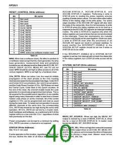
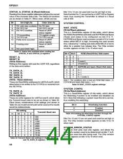
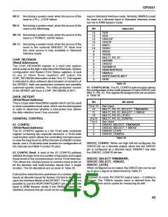
TEST_CONTROL (Write address)
Bit name
Bit
15 to 12 Not used
11 to 9
PATH_SEL<2:0>
EN_SCANPATH
Not used
TEST_CACODES
TEST_DATA
TEST_SOURCE
TM_TEST
FE_TEST
EN_DUMMYTICS
EN_DUMMYDUMP
8
7
6
5
4
3
2
1
0
The C/A code mixing must be disabled by setting
CODE_OFF/ONB (bits 11 in both CH5_ and
CH11_SATCNTL) to High. However, as the period of the
count is set by the DUMPs from the Code Generator, the
DCO clock to the Code Generator must be set to the
Table 27
41

 ZARLINK [ ZARLINK SEMICONDUCTOR INC ]