GP2021
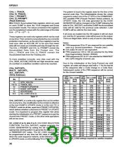
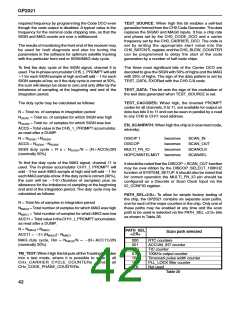
MULTI_CHANNEL_SELECT (Write address)
SYSTEM_SETUP register to set the period of the
ACCUM_INT output. ACCUM_INT is generated by a 13-
bit binary down counter which counts down to zero,
producing anACCUM_INT output. It then loads to a preset
value stored in its preset register and starts to count down
again. If the preset value is P, the count sequence is P,
P21, P22, ..., 1, 0, P, P21. Hence, the counter divides by
P11, producing an output with a period of (P11) 3 clock
period. Since the ACCUM_INT counter is clocked by the
multi-phase clock, the clock rate is either 7 3 clock period
(nominally 40MHz, i.e. 25ns) for Real_lnput mode, or 6 3
clock period (nominally 35MHz, i.e. 28.571429ns) for
Complex_lnput mode. The value stored in the PRESET
register can be modified in one of two ways: either by
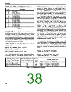
Bit
Bit name
15 to 12
Not used
11
10
9
8
7
6
5
4
3
CH11_SELECT
CH10_SELECT
CH9_SELECT
CH8_SELECT
CH7_SELECT
CH6_SELECT
CH5_SELECT
CH4_SELECT
CH3_SELECT
CH2_SELECT
CH1_SELECT
CH0_SELECT
2
1
0
toggling
the
INTERRUPT_PERIOD
or
FRONT_END_MODE bits of the SYSTEM_SETUP
register, or by writing to the PROG_ACCUM_INTlocation.
Either of these actions will overwrite the previous contents
of the preset value and either one or both methods may
be used. If the Interrupt Counter detects an edge on either
the INTERRUPT_PERIOD or FRONT_END_MODE bits
it will load one of four values in to the PRESET register,
depending upon the new value of both
INTERRUPT_PERIOD and FRONT_END_MODE.These
four presets are as shown in Table 22.
Table 21
CHx_SELECT, when set High, enables the Multi-channel
write operations on CHx. This may be used to set several
channels to mostly the same conditions. For a parallel
search for one satellite, operations such as setting each
Carrier DCO to the same frequency; or during that search,
to adjust all selected channels by the same value (such as
a Code Slew to shift the code phases together to a new
search area) could use this feature.
The value for INTERRUPT_PERIOD = low and
FRONT_END_MODE = low is also that loaded on a Master
Reset. Alternatively the ACCUM_INT counter may be
loaded by writing direct to the PROG_ACCUM_INT
location. In this case the new ACCUM_INT period is as
follows:
All CHx_SELECT are set low by a (hardware or software)
master reset.
PROG_ACCUM_INT (Write address)
Bits 15 to 13: Not Used.
ACCUM_INT period (Real Input mode)
= (PROG_ACCUM_INT11)37/40MHZ)
Bits 12 to 0: ACCUM_INT Division Ratio.
ACCUM_INT period (Complex Input mode)
= (PROG_ACCUM_INT 1 1)36/(35MHz)
The PROG_ACCUM_INT register location operates in
conjunction with the INTERRUPT_PERIOD bit of the
FRONT_END_MODE
(in SYSTEM_SETUP)
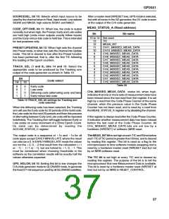
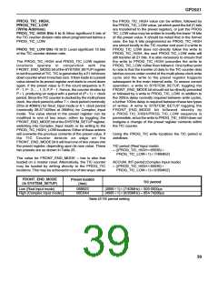
INTERRUPT_PERIOD Preset
ACCUM_INT period
(in SYSTEM_SETUP)
(hex)
Low (Real input mode)
Low (Real input mode)
High (Complex input mode)
High (Complex input mode)
Low
High
Low
High
0B45
1313
0B81
1379
(288511)3(7/40MHz) = 505·0500µs
(488311)3(7/40MHz) = 854·70000µs
(294511)3(6/35MHz) = 505·02857µs
(498511)3(6/35MHz) = 854·74286µs
Table 22 ACCUM_INT period settings
38

 ZARLINK [ ZARLINK SEMICONDUCTOR INC ]