GP2021
PROG_TIC_HIGH,
the PROG_TIC_HIGH value can be written, followed by
the PROG_TIC_LOW value, (at which point the full 21 bits
are transferred to the preset register), or just the PROG
TiC_LOW value may be written to modify the lower 16 bits
of the preset value. It should be noted that in the former
case, the top 5 bits programmed as PROG_TIC_HIGH
are stored locally to the TIC counter and even if a write to
PROG_TIC_LOW does not directly follow the write to
PROG_TIC_HIGH, the next PROG TIC_LOW write will
still transfer all 21 bits. It is also necessary to ensure that
the write to PROG_TIC_HIGH precedes the write to
PROG_TIC_LOW, rather than follows it. One further point
to note is that the transfer of data to the TIC counter data
latches occurs under control of the multi-phase clock write
cycle and the write to the preset register happens
subsequent to the main internal write. To ensure correct
operation, a write to SYSTEM_SETUP, toggling the
FRONT_END_MODE bit should not be directly preceded
or followed by a write to PROG_TIC_LOW. In addition to
the 300ns delay normally required between write cycles,
a further 100ns delay is required between these two types
of writes. A write to SYSTEM_SETUP toggling the
FRONT_END_MODE bit followed directly by
a PROG TIC_HIGH/PROG_TIC_LOW sequence is
permissible, since the write to PROG_TIC_HIGH does not
instigate a change of the preset register contents within
the TIC counter.
PROG_TIC_LOW
(Write Address)
PROG_TIC_HIGH Bits 4 to 0: More significant 5 bits of
the TIC counter division ratio when programmed before a
PROG_TIC_LOW.
PROG_TIC_LOW Bits 15 to 0: Least significant 16 bits
of the TIC counter division ratio.
The PROG_TIC_HIGH and PROG_TIC_LOW register
locations operate in conjunction with the
FRONT_END_MODE bit of the SYSTEM_SETUP register
to set the period ofTIC. TIC is generated by a 21-bit binary
down counter when it reaches zero. It then loads to a preset
value stored in its preset register and starts to count down
again. If the preset value is P, the count sequence is P,
P21, P22, ..., 1, 0, P, P21. Hence, the counter divides by
P11, producing an output with a period of (P11) 3 clock
period. Since theTIC counter is clocked by the multi-phase
clock, the clock period is either 7 3clock period (nominally
25ns at 40MHz) for Real_lnput mode or 6 3 clock period
(nominally 28.571429ns at 35MHz) for Complex_lnput
mode. The value stored in the preset register can be
modified in one of two ways: either by toggling the
FRONT_END_MODE bit of the SYSTEM_SETUP register,
switching into Complex_lnput mode, or by writing to the
PROG_TIC_HIGH/_LOW locations. Either of these actions
will overwrite the previous contents of the preset value. If
the TIC Counter detects an edge on the
FRONT_END_MODE bit it will load one of two values into
the preset register, depending upon its new value. These
two presets are as shown in Table 23.
Using the PROG_TIC write locations the TIC period is
asfollows:
TIC period (Real Input mode)
= ((PROG_TIC_HIGH365536)1
PROG_TIC_LOW11)37/40MHZ)
The value for FRONT_END_MODE = low is also that
loaded on a master reset. Alternatively, the TIC counter
may be loaded by writing directly to the PROG_TIC
locations. This may be achieved in one of two ways: either
ACCUM_INT period (Complex Input mode)
= ((PROG_TIC_HIGH365536)1
PROG_TIC_LOW11)36/35MHZ)
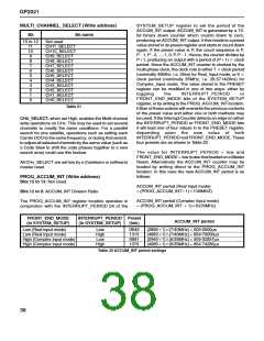
FRONT_END_MODE
(in SYSTEM_SETUP)
Preset loaded
(hex)
TIC period
Low (Real input mode)
High (Complex input mode)
08B823
08E6A4
(288511)3(7/40MHz) = 505·0500µs
(498511)3(6/35MHz) = 854·74286µs
Table 23 TIC period setting
39

 ZARLINK [ ZARLINK SEMICONDUCTOR INC ]