Philips Semiconductors
Preliminary specification
320 macrocell SRAM CPLD
PZ3320C/PZ3320N
resetn active-high and OE active-low, or resetn active-low and OE
active-high.
previous configuration program. The user must ensure that a high
output on the PZ3320 done signal does not reset the serial
EEPROM address pointer, causing the first configuration to be
reloaded.
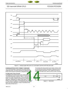
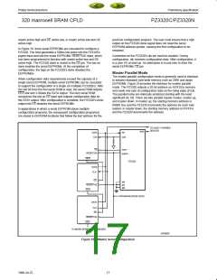
In Figure 18, three serial EEPROMs are cascaded to configure a
PZ3320. The host generates a 500ns low pulse into the PZ3320’s
prgmn input and into the serial EEPROMs’ RESET/OE input, which
has been programmed to function with resetn active-low and OE
active-high. The PZ3320 done is routed to the CE pin. The low on
done enables the serial EEPROMs. At the completion of
configuration, the high on the PZ3320’s done disables the
EEPROM(s).
Contention on the PZ3320’s din pin must be avoided. During
configuration, din receives configuration data. After configuration, it
is a user I/O at start-up. An alternative is to use ldcn to drive the
serial EEPROMs’ CE pin.
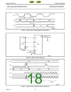
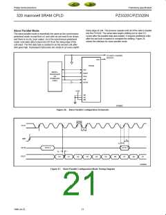
Master Parallel Mode
The master parallel configuration mode is generally used to interface
to industry-standard byte-wide memory such as 256K and larger
EEPROMs. Figure 20 provides the interface for master parallel
mode. The PZ3320 outputs a 20-bit address on A[19:0] to memory
and reads one byte of configuration data on the rising edge of rclk.
The parallel bytes are internally serialized starting with the least
significant bit, D0. There are two parallel master modes: master up,
and master down. In master up, the starting memory address is
00000 Hex and the PZ3320 increments the address for each byte
loaded. In master down, the starting memory address is FFFFFH
and the PZ3320 decrements the address.
When configuration data requirements exceed the capacity of a
single serial EEPROM, multiple serial EEPROMs can be cascaded
to support the configuration of a single (or multiple) PZ3320(s). After
the last bit from the first serial ROM is read, the serial ROM outputs
CEO low and 3-States the DATA output. The next serial ROM
recognizes the low on CE input and outputs configuration data on
the DATA output. After configuration is complete, the PZ3320’s done
output into CE disables the serial EEPROMs.
In applications in which a serial EEPROM stores multiple
configuration programs, the subsequent configuration program(s)
are stored in EEPROM locations that follow the last address for the
TO DAISY–CHAINED
DEVICES
dout
din
DATA
CLK
cclk
done
CE
RESET/OE
prgmn
CEO
PZ3320
DATA
CLK
CE
M2
M1
M0
RESET/OE
CEO
PROGRAM (FROM HOST)
DATA
CLK
CE
RESET/OE
CEO
TO MORE EEPROMS AS NEEDED
SP00658
Figure 18. Master Serial Configuration
17
1998 Jul 22

 XILINX [ XILINX, INC ]