Philips Semiconductors
Preliminary specification
320 macrocell SRAM CPLD
PZ3320C/PZ3320N
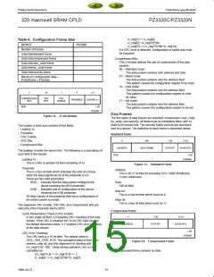
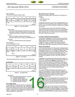
User code frame
The user code is located at address 1008D.
Bit Stream Error Checking
There are three different types of bit stream error checking in the
PZ3320:
11
274
24
32
216
1 (0)
2 (11)
– ID frame,
– Frame alignment, and
– CRC checking.
STREAM
LENGTH
DEVICE
ID
USER
CODE
STOP
BIT
ALIGN
BITS
ADDRESS UNUSED
MSB
LSB
SP00598
An optional ID data frame can be sent to a specified address in the
PZ3320. This ID Frame contains a unique code which is compared
with the value in the PZ3320 ID register. Any differences are flagged
as an ID error.
Figure 15. User code Frame
CRC checking is done on each frame if enabled by setting the
CRCen bit in the header. If there is an error, a CRC error is flagged.
When an error occurs, the PZ3320 is forced into the initialization
state, forcing initn low. The PZ3320 remains in this state until either
the resetn or prgmn pins is asserted.
Stream length:
This is a 24 bit field containing the length of the data stream
transmitted to configure all of the devices in the daisy chain.
This field is only used by a PZ3320 if it is in the master mode.
Device ID:
This is a 32-bit field containing PZ3320 device ID:
492 SBGA: 0000_001_001_101000_1_000_00000010101_1
PZ3320 CONFIGURATION MODES
The method for configuring the PZ3320 is selected by the M0, M1,
and M2 inputs. The M3 input is used to select the frequency of the
internal oscillator, which is the source for cclk in master
User code:
This is a 216 bit field reserved for user information.
configuration modes. The nominal frequencies of the internal
oscillator are 1.25MHz and 10MHz. The 1.25MHz frequency is
selected when the M3 input is unconnected or driven to a high state.
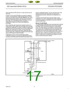
ISC code frame
The isc_code address is 1009.
11
2
272
272
1 (0)
2 (11)
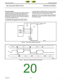
Master Serial Mode
In the master serial mode, the PZ3320 loads the configuration data
from an external serial ROM. The configuration data is either loaded
automatically at start-up or on a command to reconfigure. Serial
EEPROMs from Altera, Atmel, Lucent, Microchip, and Xilinx can be
used to configure the PZ3320 in the master serial mode. This
provides a simple four-pin interface in an eight-pin package. Serial
EEPROMs are available in 32K, 64K, 128K, 256K, and 1M bit
densities.
ADDRESS
ISC CODE
UNUSED
STOP BIT
ALIGN BITS
MSB
LSB
UNUSED
SP00599
Figure 16. ISC Frame
Configuration in the master serial mode can be done at power-up
and/or upon a configure command. The system or the PZ3320 must
activate the serial EEPROM’s RESET/OE and CE inputs. At
power-up, the PZ3320 and serial EEPROM each contain internal
power-on reset circuitry which allows the PZ3320 to be configured
without the system providing an external signal. The power-on reset
circuitry causes the serial EEPROMs’ internal address pointer to be
reset. After power-up, the PZ3320 automatically enters its
initialization phase.
The ISC frame allows the user to write an ISC code to the device.
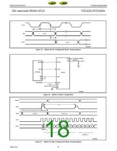
Security frame
11
2
544
1 (0)
2 (11)
SECURITY
BITS
ADDRESS
UNUSED
STOP BIT
ALIGN BITS
MSB
LSB
SP00600
The serial EEPROM/PZ3320 interface used depends on such
factors as the availability of a system reset pulse, availability of an
intelligent host to generate a configure command, whether a single
serial EEPROM is used or multiple serial ROMs are cascaded,
whether the serial EEPROM contains a single or multiple
configuration programs, etc.
Figure 17. Security Frame
Security bits:
This is a two bit field specifying the level of security.
00 – Unlimited readback allowed.
Data is read into the PZ3320 sequentially from the serial ROM. The
DATA output from the serial EEPROM is connected directly into the
din input of the PZ3320. The cclk output from the PZ3320 is
connected to the CLOCK input of the serial EEPROM. During the
configuration process, cclk clocks one data bit into the PZ3320 on
each rising edge.
01 – Readback operation allowed once.
10 – Readback operation allowed once.
11 – Readback operation is disabled.
Re-configuration
To reconfigure the PZ3320 when the device is operating in the
system, a low pulse is input into prgmn. The configuration data in
the PZ3320 is cleared, and the I/Os not used for configuration are
3-Stated. The PZ3320 then samples the mode select inputs and
begins re-configuration. When configuration is compete, done is
released, allowing it to be pulled high.
Since the data and clock are direct connects, the PZ3320/serial
EEPROM interface task is to use the system or PZ3320 to enable
the RESET/OE and CE of the serial EEPROM(s). There are several
methods for enabling the serial ROM’s RESET/OE and CE inputs.
The serial EEPROM’s RESET/OE is programmable to function with
16
1998 Jul 22

 XILINX [ XILINX, INC ]